Examples -2, Example plc-5 typed read of 10 parameter values -2, Examples – Rockwell Automation 1203-CN1 ControlNet Communications Module 1203-CN1 User Manual
Page 68
Publication 1203-5.13 – February, 2002
6-2
Using Messages
The following must be completed in the Target Device section:
•
In the Data Table Address field, enter the starting address of
the source or the destination file in the 1203-CN1 module.
Refer to Appendix C, N-File Structure, to see what data is
contained in each N-file.
•
In the ControlNet Path field, enter the node address for the
1203-CN1 module.
Important: For more information, refer to the RSLogix5 online help.
4. Read the message by viewing the N-file set in the Data Table
Address field in the PLC-5 section.
Examples
The following examples show the addition of message rungs to the
example ladder logic program for the 1305 or 1336 PLUS drive
shown in Chapter 5, PLC Ladder Logic Programming. For each type
of message, the following are shown:
•
Rung(s) in the ladder logic program.
•
Configuration in the MSG dialog box.
•
Example results.
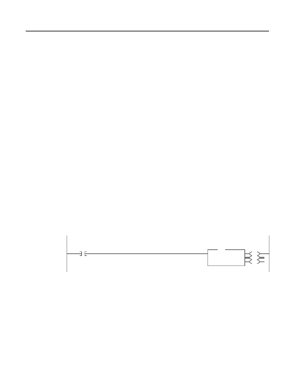
Example PLC-5 Typed Read of 10 Parameter Values
Figure 6.1 contains an example of a PCCC message. This message
allows the PLC to read ten parameters from the drive, beginning with
parameter 1.
Figure 6.1
Read Parameters Logic
In the MSG dialog box (Figure 6.2), the configuration for the
message is specified. Note the following:
•
In the Data Table Address field in the This PLC-5 section,
N20:0 is specified. This is where the results will be reported.
•
In the Size in Elements field in the This PLC-5 section, 10 is
specified. The response will be 10 elements.
•
In the Data Table Address field in the Target Device section,
N10:1 is specified. This is the location where the first parameter
value is found.
Read 10 Parameter Values starting with Parameter Number 1
0000
I:000
15
User
Input
EN
DN
ER
MSG
Read/Write Message
Control
MG15:0
Setup Screen
MSG