Required equipment and software, Example ladder logic program – Rockwell Automation 1203-CN1 ControlNet Communications Module 1203-CN1 User Manual
Page 63
Publication 1203-5.13 – February, 2002
PLC Ladder Logic Programming
5-3
Required Equipment and Software
Before creating a PLC ladder logic program, your PC should be:
•
Running RSLogix5 and RSLinx applications. Refer to
http://www.software.rockwell.com for more information on these
products.
•
Connected to and communicating with the ControlNet network
using a 1784-KTCX card, 1784-PCC card or 1770-KFC adapter.
Example Ladder Logic Program
The following is an example ladder logic program for a 1305 drive or
a 1336 PLUS drive.
Important: Consult your SCANport product’s user manual for I/O
patterns. Different SCANport products have different Logic
Command Data and Logic Status Data patterns.
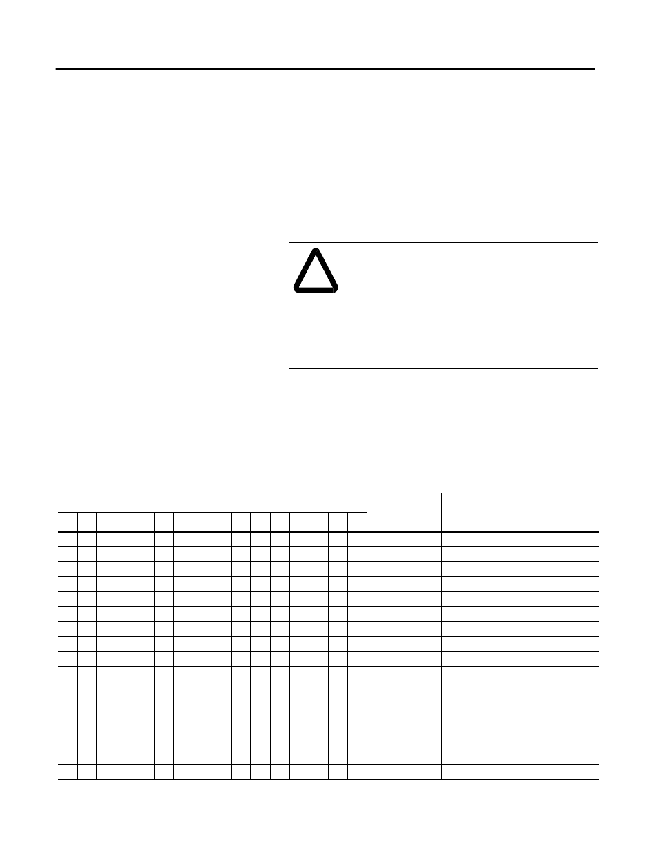
The 1305 or 1336 PLUS drive in this example accepts the following
Logic Command Data from the PLC.
!
ATTENTION: The example ladder logic program
shown in this manual is intended solely for purpose
of example. Because there are many variables and
requirements associated with any particular
installation, Rockwell Automation does not assume
responsibility or liability (to include intellectual
property liability) for actual use based upon the
example shown in this publication.
Logic Status Bits
Function
Description
15
14
13
12
11
10
9
8
7
6
5
4
3
2
1
0
X Stop
1=Stop, 0=No Operation
X
Start
1=Start, 0=No Operation
X
Jog
1=Jog, 0=No Operation
X
Clear Faults
1=Clear, 0=No Operation
X
X
Direction
00=No Operation, 01=Forward, 10=Reverse
X
Local
1=Local, 0=Multiplexed
X
MOP Increment
1=Increment MOP, 0=No Operation
X
X
Accel Rate Select
00=No Operation, 01=Rate 1, 10=Rate 2
X
X
Decel Rate Select
00=No Operation, 01=Rate 1, 10=Rate 2
X
X
X
Reference Selection 000=No Operation
001=External Reference 1 (Par 5)
010=External Reference 2 (Par 6)
011=Preset 3
100=Preset 4
101=Preset 5
110=Preset 6
111=Preset 7
X
MOP Decrement
1=Decrement MOP, 0=No Operation