Rockwell Automation 1203-CN1 ControlNet Communications Module 1203-CN1 User Manual
Page 66
Publication 1203-5.13 – February, 2002
5-6
PLC Ladder Logic Programming
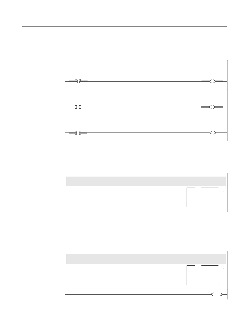
The portion of the program shown in Figure 5.4 displays the status of
the drive by reading the status information in the drive’s logic status
word and displaying it at the operator’s station.
Figure 5.4
Drive Status Display logic
The portion of the program shown in Figure 5.5 moves a Frequency
Reference to the drive. The word is scaled 0 to 32767 equals 0 to
maximum frequency. Scaling may differ for other products.
Figure 5.5
Drive Frequency Reference
The portion of the program shown in Figure 5.6 moves the drive’s
Frequency Feedback from the drive’s feedback word to the PLC. The
word is scaled 0 to 32767 equals 0 to maximum frequency. This
scaling may differ on other SCANport products.
Figure 5.6
Drive Frequency Feedback Display
Status Display Logic
0003
N12:0
0
Drive
ENABLED
Status
Bit
O:000
0
Operator
Drive Enabled
Status
Display
0004
N12:0
1
Drive
RUNNING
Status
Bit
O:000
1
Operator
Drive Running
Status
Display
0005
N12:0
7
Drive
FAULTED
Status
Bit
O:000
2
Operator
Drive Faulted
Status
Display
Frequency Reference
This rung moves a frequency reference from N7:0 to the drive's FREQUENCY REFERENCE input word at N13:1.
Frequency scaling on the 1305 AC Drive is such that 0 - 32767 = zero - max frequency.
0006
MOV
Move
Source
N7:0
16383<
Dest
N13:1
16383<
MOV
Frequency Feedback
This rung moves the drive's FREQUENCY FEEDBACK from the drive's feedback word at N12:1 to N7:1.
Frequency feedback scaling on the 1305 AC drive is such that 0 - 32767 = zero to max frequency.
0007
MOV
Move
Source
N12:1
0<
Dest
N7:1
0<
MOV
0008
END