How afe parameters are organized, File-group-parameter order – Rockwell Automation 20Y PowerFlex Active Front End User Manual
Page 92
92
Rockwell Automation Publication 20Y-UM001E-EN-P - July 2014
Chapter 4
Programming and Parameters
How AFE Parameters are
Organized
The LCD HIM displays parameters in a File-Group-Parameter or
Numbered List
view order. To switch display mode, access the Main Menu, press
the
key and release it, and while the cursor is on the parameter selection,
press the
key. In addition, parameter 090 [Param Access Lvl] can be set to
display basic parameters (Basic view) or all parameters (Advanced view).
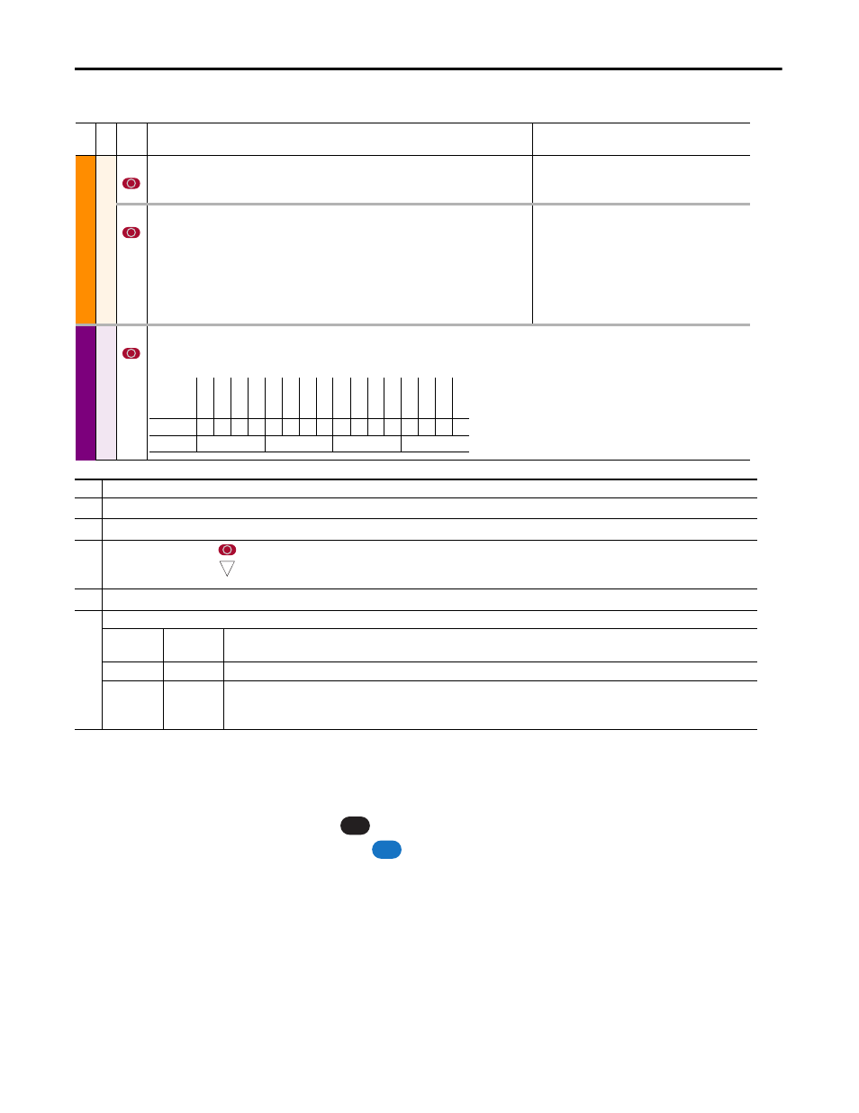
File-Group-Parameter Order
This simplifies programming by grouping parameters that are used for similar
functions. The parameters are organized into files. Each file is divided into
groups, and each group contains a set of parameters related to a specific purpose.
By default, the LCD HIM displays parameters by File-Group-Parameter view.
Fil
e
Gr
oup
No.
Parameter Name & Description
Values
DYN
A
M
IC C
O
NTR
O
L
Co
nt
ro
l M
od
es
040
[Nom Input Volt]
Sets the incoming supply voltage level used to calculate the DC voltage level for charging control.
Default:
Min/Max:
Units:
Based on Unit Rating
Based on Unit Rating
1V AC
046
[Start/Stop Mode]
Selects the operating mode for the regenerative unit.
0 (Normal) = The converter starts only with a Run request.
1 (Auto) = The converter starts regenerative operation automatically whenever the DC Voltage is
higher than the DC Voltage reference and stops when there is no regeneration. The converter starts
by a Run or Start command. To avoid starting, a digital input can be configured to ‘enable’. Auto
mode selection is allowed only if an external motoring bus supply is installed to not damage the
unit.
Default:
Options:
0
0
1
Normal
Normal
Auto
COMMUNIC
AT
ION
Mask
s &
O
w
n
ers
154
[Logic Mask]
Determines which communication adapters can control the unit. If the bit for an adapter is set
to ‘0’, the adapter has no control functions except for stop.
Bit
Definition
DP
I P
or
t 5
DP
I P
or
t 4
DP
I P
or
t 3
DP
I P
or
t 2
DP
I P
or
t 1
Dig
ita
l In
Default
x
x
x
x
x
x
x
x
x
x
1
1
1
1
1
1
Bit
15 14 13 12 11 10 9
8
7
6
5
4
3
2
1
0
0 = Control Permitted
1 = Control Masked
x = Reserved
➊
➌
➋
➎
➍
No.
Description
➊
File – Lists the major parameter file category.
➋
Group – Lists the parameter group within a file.
➌
No. – Parameter number.
= Parameter value cannot be changed until the AFE is stopped.
= 32 bit parameter.
➍
Parameter Name & Description – Parameter name as it appears on an LCD HIM, with a brief description of the parameter function.
➎
Values – Defines the various operating characteristics of the parameter. Three parameter types exist.
ENUM
Default:
Options:
Lists the value assigned at the factory. Read Only = no default.
Displays the available programming selections.
Bit
Bit:
Lists the bit place holder and definition for each bit.
Numeric
Default:
Min/Max:
Units:
Lists the value assigned at the factory. Read Only = no default.
The range (lowest and highest setting) possible for the parameter.
Unit of measure and resolution as shown on the LCD HIM.
32
ALT
Sel