Dc bus output wiring, Figure 31 – Rockwell Automation 20Y PowerFlex Active Front End User Manual
Page 66
66
Rockwell Automation Publication 20Y-UM001E-EN-P - July 2014
Chapter 2
AFE in IP21 Rittal Enclosure—Installation/Wiring
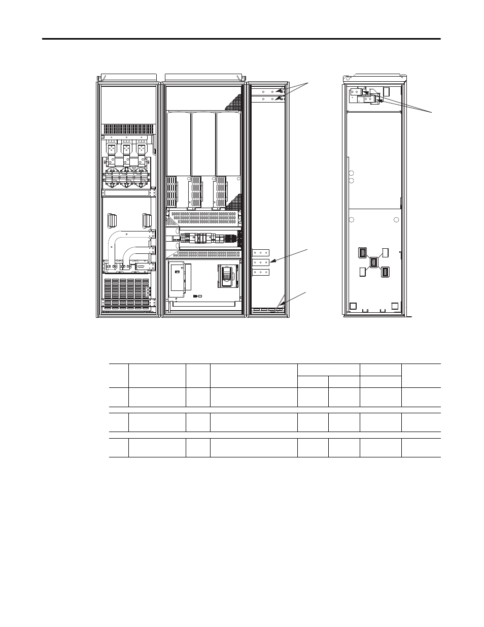
Figure 31 - AFE Frame 13 Power Terminal Locations in IP21 Rittal Enclosure
Table 13 - AFE Frame 13 Power Terminal Specifications in IP21 Rittal Enclosure
DC Bus Output Wiring
The length of the DC bus connections between the AFE and the drive or drives
must be minimized to keep the bus inductance low for reliable system operation.
For more information, see Drives in Common Bus Configurations, publication
DRIVES-AT002.
(Shown with
enclosure doors
removed)
FRONT VIEW
RIGHT SIDE VIEW
Item
Name
Frame
Description
Wire Size Range
(1)
(2)
Torque
Terminal Bolt
Size
(3)
(4)
Maximum
Minimum
Recommended
➊
Input Power Terminals
L1, L2, L3
13
Input power
300 mm
2
(600 MCM)
2.1 mm
2
(14 AWG)
70 N•m
(620 lb•in)
M12
➋
13
Terminating point for wiring shields
300 mm
2
(600 MCM)
2.1 mm
2
(14 AWG)
40 N•m
(354 lb•in)
M10
➌
DC Bus
(DC–, DC+)
13
DC output
300 mm
2
(600 MCM)
2.1 mm
2
(14 AWG)
70 N•m
(620 lb•in)
M12
(1) Maximum/minimum sizes that the terminals will accept - these are not recommendations.
(2) Do not exceed maximum wire size. Parallel connections may be required.
(3) These connections are bus bar type terminations and require the use of lug type connectors.
(4) Apply counter torque to the nut on the other side of terminations when tightening or loosening the terminal bolt to avoid damage to the terminal.