Rockwell Automation 20Y PowerFlex Active Front End User Manual
Page 17
Rockwell Automation Publication 20Y-UM001E-EN-P - July 2014
17
Preface
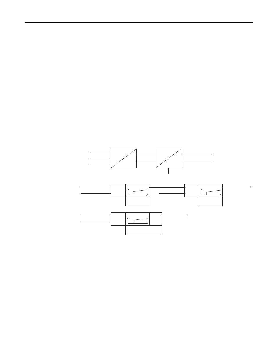
The output of the DC voltage controller is the active current reference, which is
compared to the measured active current. The error between them is the input
for the active current controller. The output of the active current controller
changes the modulation index and controls the inverter voltage.
The reactive current reference can be used for reactive power compensation. A
positive reactive current reference indicates inductive and a negative reactive
current reference indicates capacitive reactive power compensation. The default
value of the reactive current reference parameter is zero. The set value of the
reactive current reference is compared to its measured value and the error is fed to
the PI regulator. The PI regulator is also referred to as the ‘synchronizing
controller’ because its function is to keep the inverter synchronized with line
supply. The frequency reference to the AFE is derived from the reactive current
controller output. Normally the active current Kp, active current Ki, reactive
current Kp, and reactive current Ki default values of the two current controllers
are satisfactory with the standard LCL filter, and should not be changed.
Figure 3 - AFE Block Diagram
I
L1
3
2
_
_
_
PI
PI
PI
PD
Park Transform
DC Volt Measured
DC Volt Reference
Reactive Current Ref
Reactive Current
Active Current Ref
Modulation Index
Active Current
Freq Reference
DC Volt Kp
DC Volt Ki
Reactive Curr Kp
Reactive Curr Ki
Active Curr Kp
Active Curr Ki
Cartesian
Modulator Voltage Angle
Reactive Current
Active Current
Polar
I Alpha
I Beta
I
L2
I
L3