Safety ground - pe and shield termination - shld, Fuses and circuit breakers – Rockwell Automation 20Y PowerFlex Active Front End User Manual
Page 30
30
Rockwell Automation Publication 20Y-UM001E-EN-P - July 2014
Chapter 1
AFE in IP20 2500 MCC Style Enclosure—Installation/Wiring
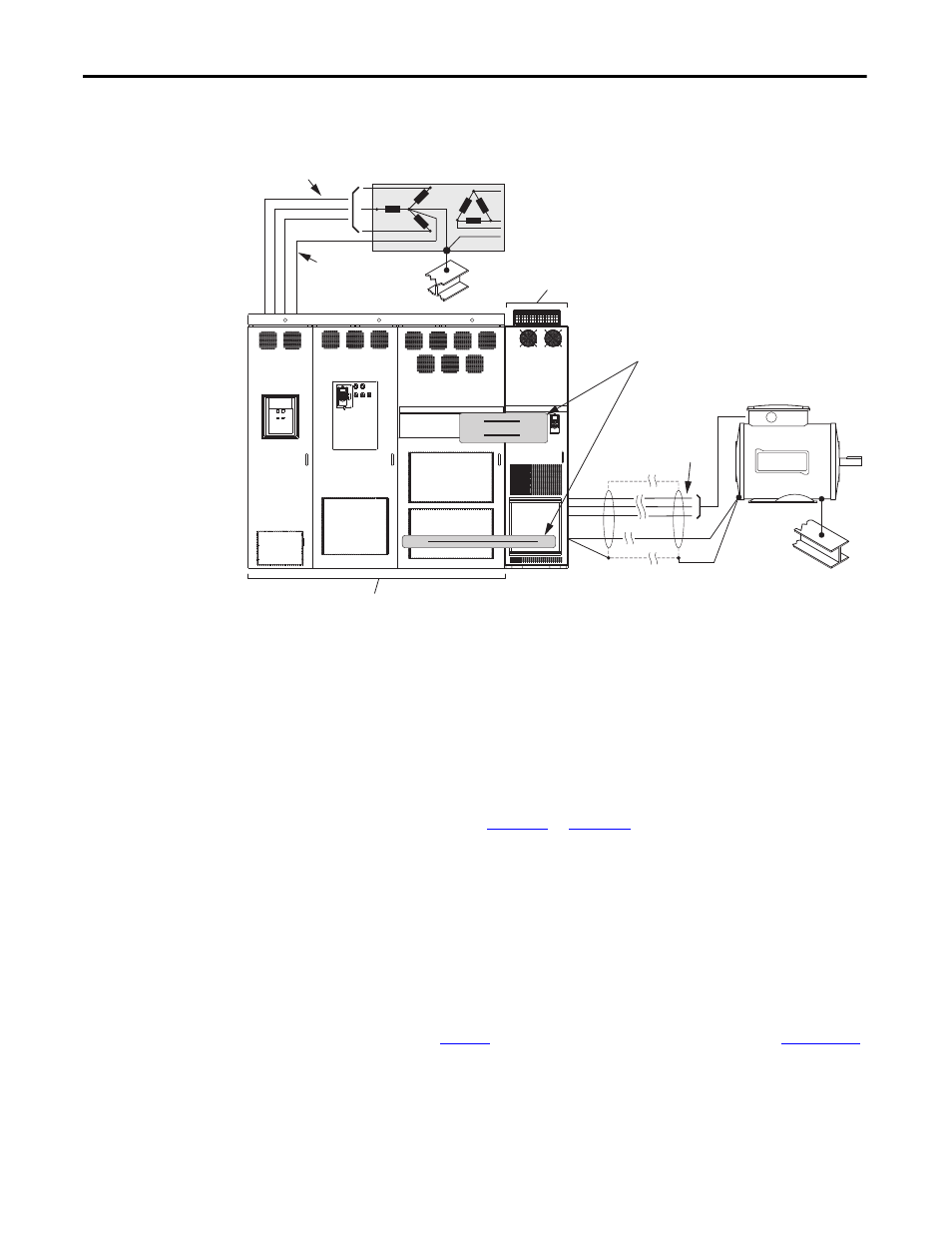
Figure 11 - Typical Grounding Example for AFE Frame 13 in IP20 2500 MCC Style Enclosure
Safety Ground - PE and Shield Termination - SHLD
This is the safety ground for the AFE that is required by code. This point must be
connected to adjacent building steel (girder or joist), a floor ground rod or bus
bar (see above). Grounding points must comply with national and local industrial
safety regulations and/or electrical codes.
The Shield terminal (
) provides a grounding point for the
AFE cable shield. It must be connected to an earth ground by a separate
continuous lead. The drive cable shield must be connected to this terminal on the
AFE end and the drive frame on the drive end. Use a shield terminating or EMI
clamp to connect the shield to this terminal.
Fuses and Circuit Breakers
The IP20 2500 MCC Style enclosure for the AFE includes AC input fusing,
input circuit breaker (Q0), an input contactor (K1), and DC bus output fusing.
The contactor is used for precharge operation. For details on precharge
operation, see
. For fuse and circuit breaker information, see
Local/national electrical codes can determine additional requirements for the
installations.
PE
PowerFlex 750-Series Drive or PowerFlex 7-Class Drive
(can be located on the right or left side of the AFE;
PowerFlex 755 Frame 8 drive shown on right side)
Customer wiring or DC bus
bar splice required to connect
the AFE to the drive.
SHLD
To Line PE
PowerFlex AFE Frame 13
DC+
DC-
DC+
DC-
PE
PE
R (L1), S (L2), T (L3)
U (T1), V (T2), W (T3)