Frame 10 or frame 13 power structure, Using the afe with powerflex drives, Control wiring – Rockwell Automation 20Y PowerFlex Active Front End User Manual
Page 40: Using the afe with powerflex drives control wiring, Figure 19 on
40
Rockwell Automation Publication 20Y-UM001E-EN-P - July 2014
Chapter 1
AFE in IP20 2500 MCC Style Enclosure—Installation/Wiring
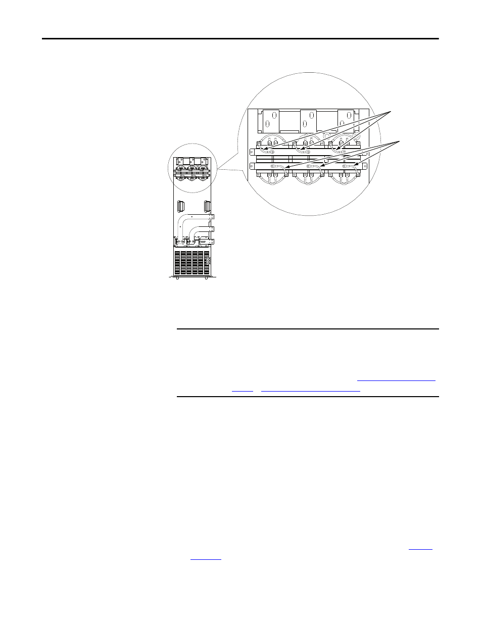
Figure 19 - AFE Frame 13 LCL Filter Common Mode Capacitor Jumper Locations
Frame 10 or Frame 13 Power Structure
Using the AFE with
PowerFlex Drives
When the Active Front End is used with drives that have common mode
capacitors (for example, PowerFlex 7-Class or PowerFlex 750-Series drives), the
common mode capacitors of these drives must be disconnected. See the
documentation for the respective drives.
When supplying power to PowerFlex drives of different frame sizes on the same
DC bus, additional bus capacitance may be needed. For details, see Drives in
Common Bus Configurations, publication DRIVES-AT002.
Control Wiring
The AFE in a IP20 2500 MCC Style enclosure is factory wired and programmed
to operate from the operator switches on the front of the enclosure. See
for I/O terminal designations. Only when customized (or remote)
Remove Three
Jumpers
Remove Three
Jumpers
FRONT VIEW
OF LCL FILTER
IMPORTANT
The Frame 10 or Frame 13 AFE in a IP20 2500 MCC Style enclosure is shipped
from the factory with the common mode capacitors removed so the user need
not do this. However, when a power structure is replaced, the common mode
capacitors in the new power structure must be removed by the user prior
to installation. For instructions to do this, see
Frame 13 Power Structure on page 71
.