Cable trays and conduit – Rockwell Automation 20Y PowerFlex Active Front End User Manual
Page 33
Rockwell Automation Publication 20Y-UM001E-EN-P - July 2014
33
AFE in IP20 2500 MCC Style Enclosure—Installation/Wiring
Chapter 1
Cable Trays and Conduit
If cable trays or large conduits are to be used, refer to guidelines presented in
Wiring and Grounding Guidelines for Pulse Width Modulated (PWM) AC
Drives, publication DRIVES-IN001.
Selecting and Verifying Control Transformer Voltage
The control transformer in the AFE is used to match the input AC line voltage of
the AFE in an IP20 2500 MCC Style enclosure to the 230V and 120V control
voltage.
Verify that the control voltage is set appropriately for the supplied AC line
voltage. If necessary, change the control voltage using this procedure.
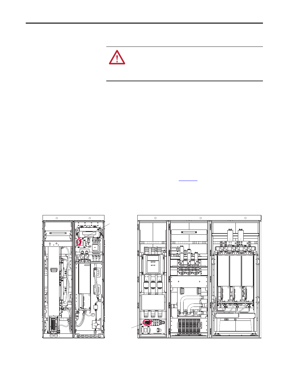
1.
Locate the X3 terminal block (
Figure 12 - X3 Terminal Block Location for AFE in IP20 2500 MCC Style Enclosure
ATTENTION: To avoid a possible shock hazard caused by induced voltages,
unused wires in the conduit must be grounded at both ends. For the same reason,
if a drive sharing a conduit is being serviced or installed, all drives using this
conduit must be disabled. This helps minimize the possible shock hazard from
‘cross coupled’ motor leads.
X3 Terminal
Block Location
Frame 10
(shown with enclosure
doors removed)
FRONT VIEW
FRONT VIEW
Frame 13
(shown with enclosure
doors removed)
X3 Terminal
Block Location
X3 Terminal
Block Location