Utility file – Rockwell Automation 20Y PowerFlex Active Front End User Manual
Page 101
Rockwell Automation Publication 20Y-UM001E-EN-P - July 2014
101
Programming and Parameters
Chapter 4
Utility File
Fil
e
Gr
oup
No.
Parameter Name & Description
Values
U
TIL
IT
Y
Co
nv
er
te
r Me
mor
y
090
[Param Access Lvl]
Selects the parameter display level.
0 (Basic) = Reduced parameter set.
1 (Advanced) = Full parameter set.
Default:
Options:
0
0
1
Basic
Basic
Advanced
091
[Reset to Defaults]
Resets parameters to factory defaults except parameters 093 [Language] and
090 [Param Access Lvl].
0 (Ready) = A new value may be entered.
1 (Factory) = Resets parameters to factory defaults.
2 (Low Voltage) = Resets parameters to factory defaults and configures parameters for a:
• 400/480V AFE unit for 400V operation.
• 600/690V AFE unit for 600V operation.
3 (High Voltage) = Resets parameters to factory defaults and configures parameters for a:
• 400/480V AFE unit for 480V operation.
• 600/690V AFE unit for 690V operation.
NOTE: The DC bus voltage must be present to set the voltage class.
Default:
Options:
0
0
1
2
3
Ready
Ready
Factory
Low Voltage
High Voltage
092
[Reset Meters]
Resets these selected meters (Motoring MWh, Regen MWh, and Elapsed Time) to zero.
Default:
Options:
0
0
1
2
3
Ready
Ready
Motoring MWh
Regen MWh
Elapsed Time
093
[Language]
Limited to English language only.
Default:
Options:
0
0
1
Not Selected
Not Selected
English
094
[Voltage Class]
Displays the last ‘Reset To Defaults’ operation.
Default:
Options:
Read Only
0 = Low Voltage
1 = High Voltage
Di
ag
n
os
ti
cs
095
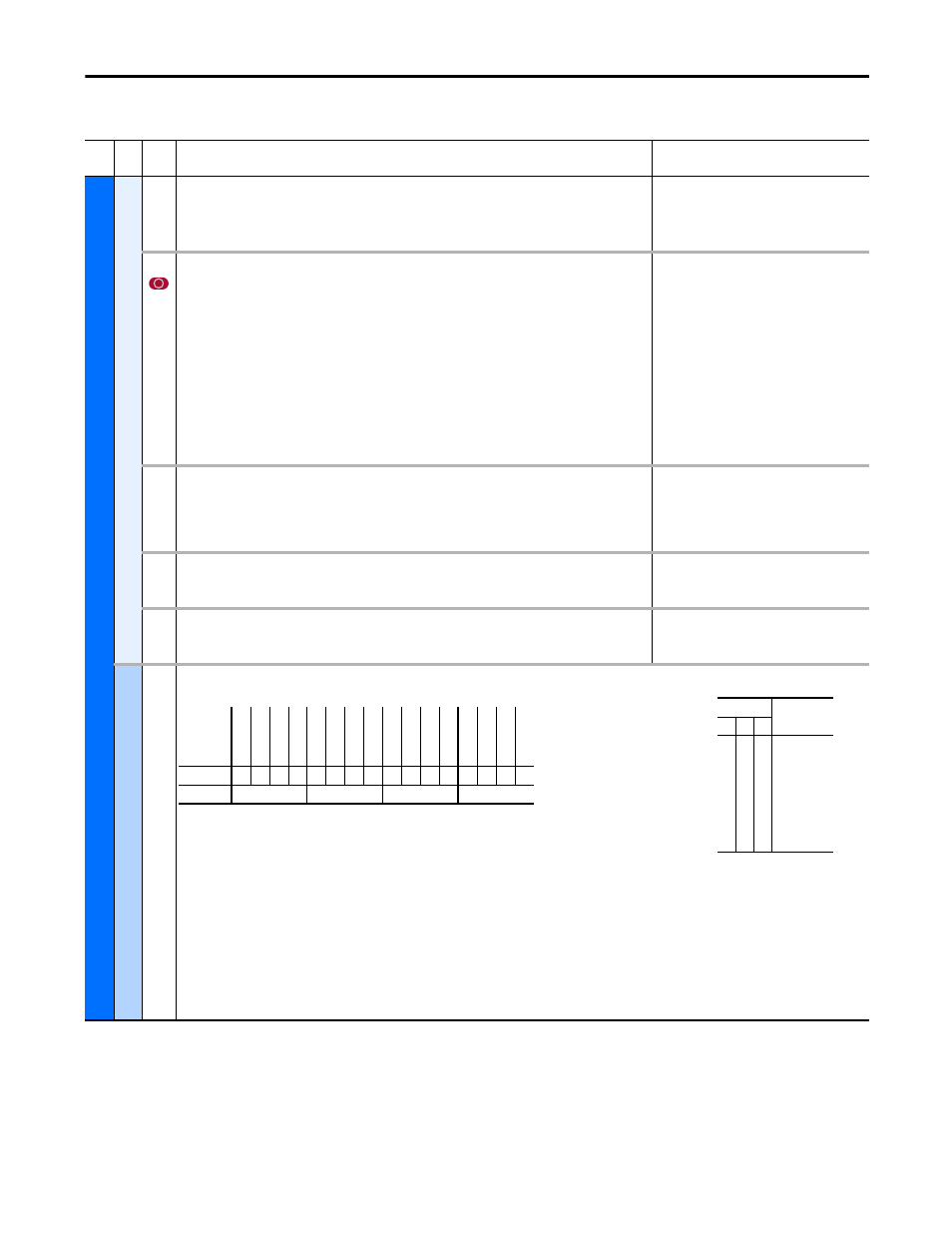
[Cnvrtr Status 1]
Displays the present operating condition of the AFE.
• Bit 0 (Ready) indicates all inhibits are cleared.
• Bit 1 (Active) indicates the AFE is modulating.
• Bit 2 (Motoring) indicates the AFE is running in motoring mode.
• Bit 3 (Regenerating) indicates the AFE is regenerating power to the AC line.
• Bit 4 (In Precharge) indicates the AFE is in precharging status.
• Bit 5 (Droop Active) indicates that the droop function for AFE paralleling is activated.
• Bit 6 (Alarm) indicates the AFE has detected an alarm.
• Bit 7 (Faulted) indicates the AFE has detected a fault.
• Bit 8 (At Reference) indicates the DC bus voltage is at the command value.
• Bit 9 (Mot CurLim) indicates the AFE exceeds the current limit in motoring mode.
• Bit 10 (Regen CurLim) indicates the AFE exceeds the current limit in regenerative mode.
• Bit 11 (Cmd Delayed) indicates pending start command.
• Bits 12…14 indicate the DC bus voltage reference selection.
Read Only
Bit
Definition
DC
Vo
lt
Re
fD2
DC
Vo
lt
Re
fD1
DC
Vo
lt
Re
fD0
Cm
d D
ela
yed
Re
gen C
urLim
Mot C
urLim
At
R
ef
er
en
ce
Fa
ul
te
d
Alar
m
D
roop A
ctiv
e
In Pr
ec
har
ge
Regener
ating
Mot
ori
ng
Ac
tive
Re
ad
y
Default
x
0
0
0
0
0
0
0
0
0
0
0
0
0
0
0
Bit
15 14 13 12 11 10 9
8
7
6
5
4
3
2
1
0
1 = Condition True
0 = Condition False
x = Reserved
Bits
Description
14 13 12
0
0
0
0
1
1
1
1
0
0
1
1
0
0
1
1
0
1
0
1
0
1
0
1
DC Volt Ref
Analog In1
Analog In2
DPI Port 1
DPI Port 2
DPI Port 3
DPI Port 4
DPI Port 5