Signal and control wire types – Rockwell Automation 20Y PowerFlex Active Front End User Manual
Page 41
Rockwell Automation Publication 20Y-UM001E-EN-P - July 2014
41
AFE in IP20 2500 MCC Style Enclosure—Installation/Wiring
Chapter 1
control is required, will the control wiring and correspondent digital I/O
parameter setting need to be changed.
Here are some important points to remember about I/O wiring:
•
Always use copper wire.
•
Wire with an insulation rating of 600V or greater is recommended.
•
Control and signal wires must be separated from power wires by at least 0.3
meters (1 foot).
•
When it is unavoidable to cross control and signal wires with power wires,
always cross power wires at a 90° angle.
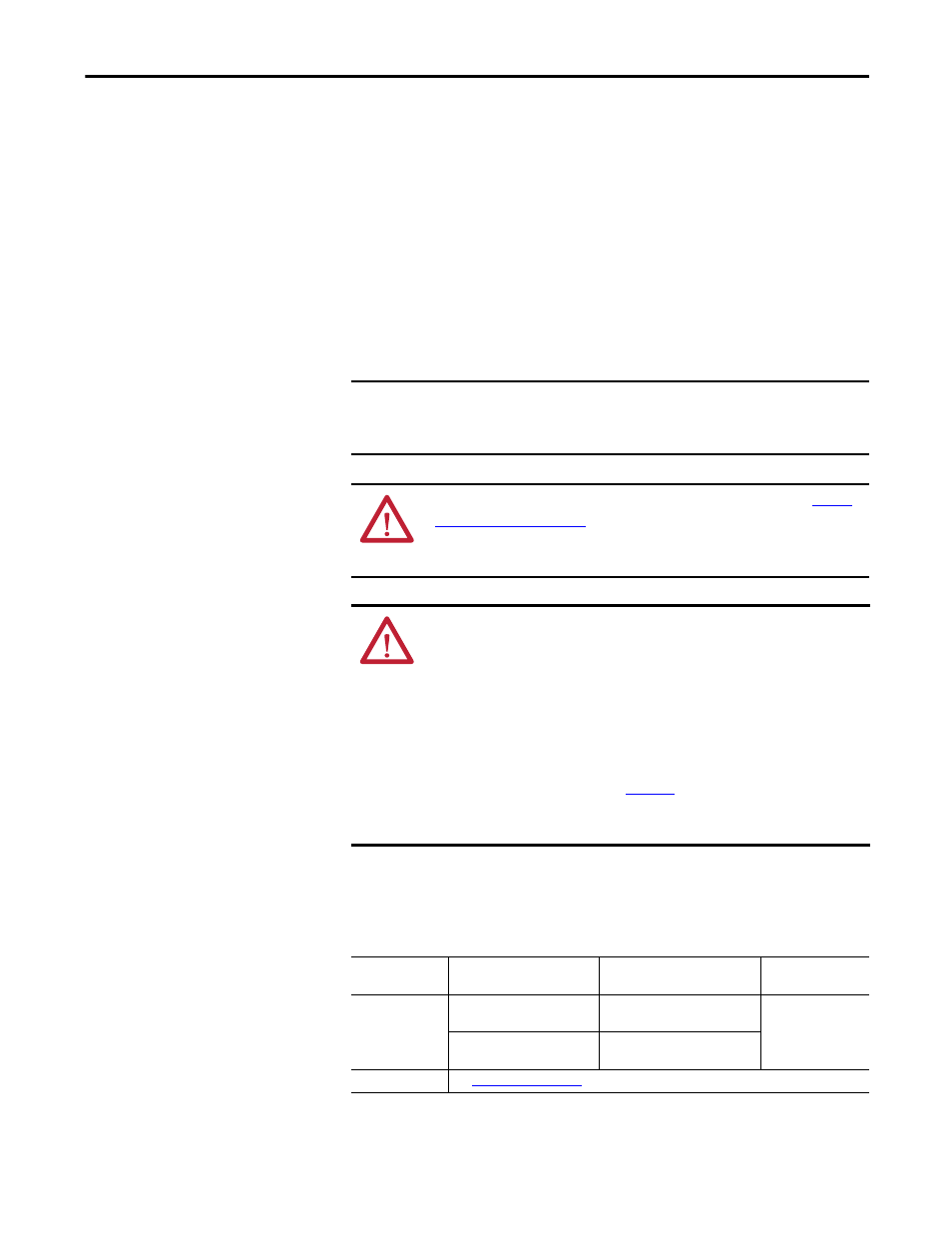
Signal and Control Wire Types
Table 4 - Recommended Signal Wire for AFE in IP20 2500 MCC Style Enclosure
IMPORTANT
I/O terminals labeled ‘(–)’ or ‘Common’ are not referenced to earth ground.
They are designed to greatly reduce common mode interference. Grounding
these terminals can cause signal noise.
ATTENTION: Inputs must be configured with software and jumpers (see
). Also, configuring an analog input for 0-20 mA
operation and driving it from a voltage source can cause component damage.
Verify proper configuration before applying input signals.
ATTENTION: It is important to disable the variable frequency drives that are
connected to the AFE output when the AFE is not active (not modulating). This
can be done by either connecting the 'Inverter Enable' output of the AFE to each
variable frequency drive’s enable input, or by enabling parameter 132 [Contact
Off Cnfg] to force the main contactor off in case of a fault. This ensures that once
the AFE stops modulating, there is no motoring current flowing through the AFE
IGBT diodes. Failure to disable the AFE output can result in component damage
or a reduction in product life.
When enabling parameter 132, see
for details. The AFE is shipped with
parameter 132 disabled. This will not stop or shut down DC output when a fault
occurs.
Signal Type
Wire Type(s)
Description
Minimum
Insulation Rating
Analog I/O
Belden 8760/9460
(or equivalent)
0.5 mm
2
(22 AWG), twisted pair,
100% shield with drain
(1)
(1) If the wires are short and contained within an enclosure that has no sensitive circuits, the use of shielded wire may not be necessary,
but is always recommended.
300V, 75…90 °C
(167…194 °F)
Belden 8770
(or equivalent)
0.5 mm
2
(22 AWG), 3 conductor,
shielded for remote pot only
EMC Compliance
See
for details.