Cable trays and conduit – Rockwell Automation 20Y PowerFlex Active Front End User Manual
Page 63
Rockwell Automation Publication 20Y-UM001E-EN-P - July 2014
63
AFE in IP21 Rittal Enclosure—Installation/Wiring
Chapter 2
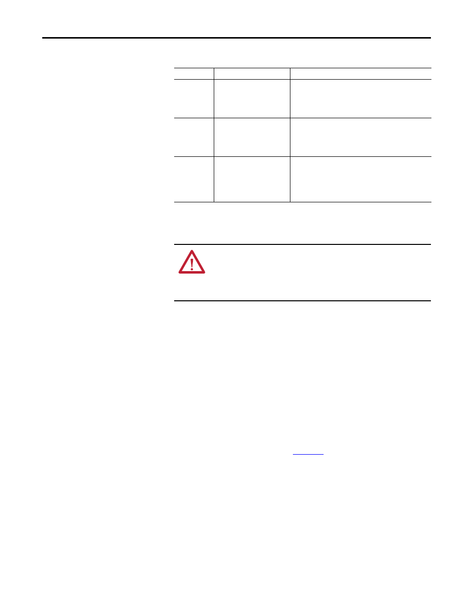
Table 11 - Recommended Shielded/Armored Wire for AFE in IP21 Rittal Enclosure
Cable Trays and Conduit
If cable trays or large conduits are to be used, refer to guidelines presented in
Wiring and Grounding Guidelines for Pulse Width Modulated (PWM) AC
Drives, publication DRIVES-IN001.
Selecting and Verifying Control Transformer Voltage
The control transformer in the AFE is used to match the input AC line voltage of
the AFE in an IP21 Rittal enclosure to the 230V control voltage.
Verify that the control voltage is set appropriately for the supplied AC line
voltage. If necessary, change the control voltage using this procedure.
1.
Locate the X3 terminal block (
Location
Rating/Type
Description
Standard
(Option 1)
1000V, 90 °C (194 °F) XHHW2/
RHW-2 Anixter B29528-B29532,
Belden 29528-29532, or
equivalent
• Four tinned copper conductors with XLPE insulation.
• Copper braid/aluminum foil combination shield and tinned
copper drain wire.
• PVC jacket.
Standard
(Option 2)
Tray rated 1000V, 90 °C (194 °F)
RHH/RHW-2 Anixter OLFLEX-
76xxx03 or equivalent
• Three tinned copper conductors with XLPE insulation.
• corrugated copper tape with three bare copper grounds in
contact with shield.
• PVC jacket.
Class I & II;
Division I & II
Tray rated 1000V, 90 °C (194 °F)
RHH/RHW-2 Anixter 7VFD-xxxx
or equivalent
• Three bare copper conductors with XLPE insulation and
impervious corrugated continuously welded aluminum
armor.
• Black sunlight resistant PVC jacket overall.
• Three copper grounds.
ATTENTION: To avoid a possible shock hazard caused by induced voltages,
unused wires in the conduit must be grounded at both ends. For the same reason,
if a drive sharing a conduit is being serviced or installed, all drives using this
conduit must be disabled. This helps minimize the possible shock hazard from
‘cross coupled’ motor leads.