Rockwell Automation 20Y PowerFlex Active Front End User Manual
Page 104
104
Rockwell Automation Publication 20Y-UM001E-EN-P - July 2014
Chapter 4
Programming and Parameters
U
TIL
IT
Y
Di
ag
n
os
ti
c
108
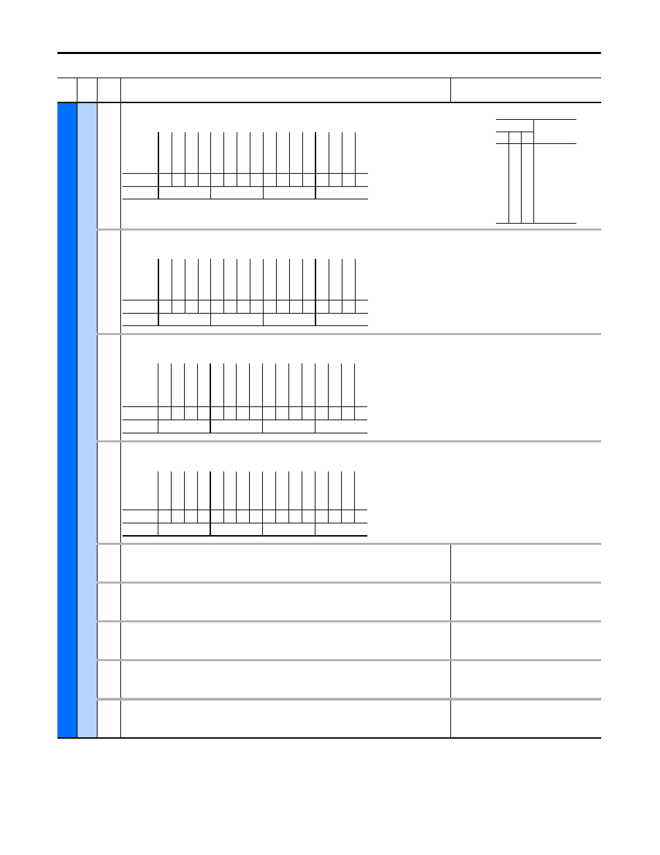
[Status 1 @ Fault]
Captures and displays the bit pattern of parameter 095 [Cnvrtr Status 1] at the time of the last fault.
Read Only
109
[Status 2 @ Fault]
Captures and displays the bit pattern of parameter 096 [Cnvrtr Status 2] at the time of the last fault.
Read Only
110
[Alarm 1 @ Fault]
Captures and displays the bit pattern of parameter 097 [Cnvrtr Alarm 1] at the time of the last fault.
Read Only
111
[Alarm 2 @ Fault]
Captures and displays the bit pattern of parameter 098 [Cnvrtr Alarm 2] at the time of the last fault.
Read Only
112
[Testpoint 1 Sel]
Selects the function whose value is displayed in parameter 113 [Testpoint 1 Data]. These are internal values
that are not accessible through parameters.
Default:
Min/Max:
Units:
499
0/65535
None
113
[Testpoint 1 Data]
Displays the present value of the function selected in parameter 112 [Testpoint 1 Sel].
Default:
Min/Max:
Units:
Read Only
-/+32767
None
114
[Testpoint 2 Sel]
Selects the function whose value is displayed in parameter 115 [Testpoint 2 Data]. These are internal values
that are not accessible through parameters.
Default:
Min/Max:
Units:
499
0/65535
None
115
[Testpoint 2 Data]
Displays the present value of the function selected in parameter 114 [Testpoint 2 Sel].
Default:
Min/Max:
Units:
Read Only
-/+32767
None
116
[Cnvrtr OL Count]
Displays the accumulated percentage of AFE overload. Continuously operating the AFE over the set level will
increase this value to 100% and cause an AFE fault.
Default:
Min/Max:
Units:
Read Only
0.1%/+100.0%
0.1%
Fil
e
Gr
oup
No.
Parameter Name & Description
Values
Bit
Definition
DCV
ol
tRe
fD
2
DCV
ol
tRe
fD
1
DCV
ol
tRe
fD
0
Cm
d D
ela
ye
d
Re
ge
n C
urLim
Mot C
urLi
m
At
Re
fer
en
ce
Fa
ul
te
d
Alarm
D
roop A
ctiv
e
In P
rec
har
ge
Reg
enera
ting
Mot
oring
Ac
tiv
e
Re
ady
Default
x
0
0
0
0
0
0
0
0
0
0
0
0
0
0
0
Bit
15 14 13 12 11 10 9
8
7
6
5
4
3
2
1
0
1 = Condition True
0 = Condition False
x = Reserved
Bits
Description
14 13 12
0
0
0
0
1
1
1
1
0
0
1
1
0
0
1
1
0
1
0
1
0
1
0
1
DC Volt Ref
Analog In1
Analog In2
DPI Port 1
DPI Port 2
DPI Port 3
DPI Port 4
DPI Port 5
Bit
Definition
DPI
a
t 500
k
Au
to
Rs
t A
ct
Au
to
Rs
t C
td
n
ModI
ndexLim
Ac
tiv
e
Re
ady
Default
x
x
0
x
x
x
0
0
x
x
x
x
x
0
0
0
Bit
15 14 13 12 11 10 9
8
7
6
5
4
3
2
1
0
1 = Condition True
0 = Condition False
x = Reserved
Bit
Definition
Ov
er
lo
ad
DCB
usHiAla
rm
DCB
usL
oAl
ar
m
DCRe
fHighLi
m
DCRe
fL
ow
Li
m
LC
L F
an
S
to
p
Heatsi
nk
O
vT
p
LineS
ync
Fa
il
An
lg
In
L
os
s
DC UnderV
ol
t
Pr
ec
hr
g Ac
tv
Default
x
0
x
0
0
0
0
0
0
0
0
0
0
0
0
0
Bit
15 14 13 12 11 10 9
8
7
6
5
4
3
2
1
0
1 = Condition True
0 = Condition False
x = Reserved
Bit
Definition
Co
nt
ac
t Fd
bk
Di
gI
nC
on
flc
t
Default
x
x
x
x
x
x
x
x
x
x
x
0
x
x
0
0
Bit
15 14 13 12 11 10 9
8
7
6
5
4
3
2
1
0
1 = Condition True
0 = Condition False
x = Reserved