Understanding the i/o image, Understanding the i/o image -7 – Rockwell Automation 22-COMM-P PowerFlex Profibus Adapter User Manual
Page 67
Using Multi-Drive Mode
7-7
The Profibus specification requires that the terms input and output be
defined from the scanner’s point of view. Therefore, Output I/O is data
that is output from the scanner and consumed by the Profibus adapter.
Input I/O is status data that is produced by the adapter and consumed as
input by the scanner.
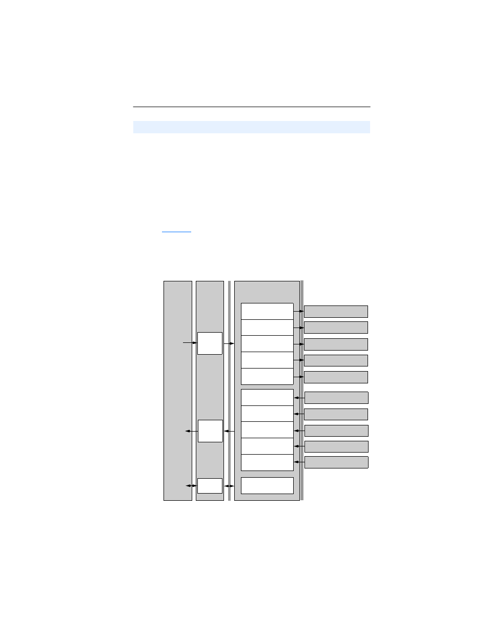
The I/O image table will vary based on the configuration of the adapter
Mode Jumper (J2) and adapter Parameter 11 - [DSI I/O Cfg]. The
image table always uses consecutive words starting at word 0.
illustrates an example of an I/O image (16-bit words) for the
adapter operated in Multi-Drive mode.
Figure 7.9 Multi-Drive Example of I/O Image
Understanding the I/O Image
Controller
Scanner
Adapter
PF 4-Class Drive 0
Profibus
DSI
Output
Image
(Write)
Input
Image
(Read)
Message
Handler
Message
Buffer
Word and I/O
0 Logic Command
1 Reference
2 Logic Command
3 Reference
4 Logic Command
5 Reference
6 Logic Command
7 Reference
8 Logic Command
9 Reference
0 Logic Status
1 Feedback
2 Logic Status
3 Feedback
4 Logic Status
5 Feedback
6 Logic Status
7 Feedback
8 Logic Status
9 Feedback
PF 4-Class Drive 0-1
PF 4-Class Drive 0-2
PF 4-Class Drive 0-3
PF 4-Class Drive 0-4
PF 4-Class Drive 0
PF 4-Class Drive 0-1
PF 4-Class Drive 0-2
PF 4-Class Drive 0-3
PF 4-Class Drive 0-4