Rockwell Automation 22-COMM-P PowerFlex Profibus Adapter User Manual
Page 100
D-12
SLC Ladder Logic Examples
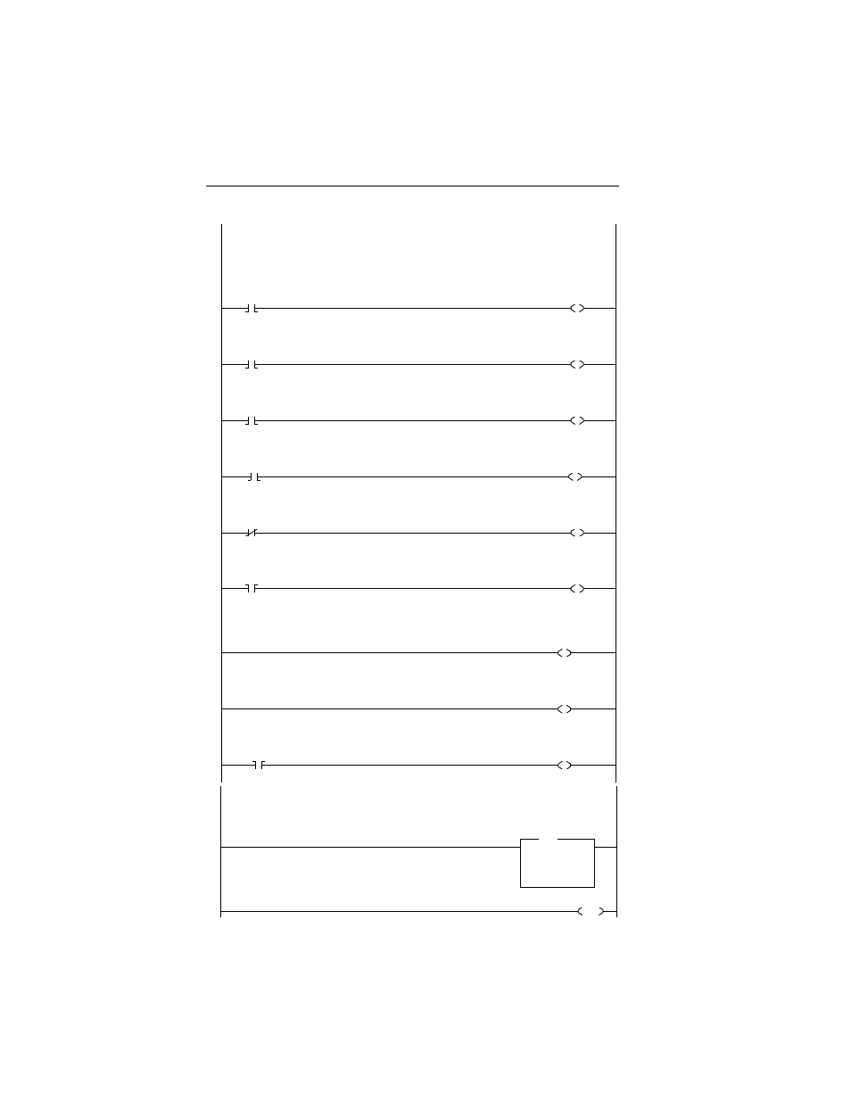
Figure D.6 Drive 0-1 Control/Reference Routine
Controlling the Logic Command word in the drive. B3:21/* bits are controlled elsewhere in the user program.
0
B3:21
0
Station 1
Stop
Command
N20:2
0
Station 1
Logic Command
STOP
1
B3:21
1
Station 1
Start
Command
N20:2
1
Station 1
Logic Command
START
2
B3:21
2
Station 1
Jog
Command
N20:2
2
Station 1
Logic Command
JOG
3
B3:21
3
Station 1
Clear Faults
Command
N20:2
3
Station 1
Logic Command
CLEAR FAULTS
4
B3:21
4
Station 1
Reverse
Command
N20:2
4
Station 1
Logic Command
FORWARD
5
B3:21
4
Station 1
Reverse
Command
N20:2
5
Station 1
Logic Command
REVERSE
To control the speed reference over the Profibus, the three Reference Select bits (bits 14-12) need to have the values 011.
6
N20:2
12
Station 1
Logic Command
REFERENCE SELECT 0
7
N20:2
13
Station 1
Logic Command
REFERENCE SELECT 1
8
B3:21
5
"Never Closed"
N20:2
14
Station 1
Logic Command
REFERENCE SELECT 2
Station 1 Speed Reference
The PowerFlex 40 parameter 38 - [Speed Reference] needs to be set to 5 ("RS485 [DSI] Port").
N19:3 is controlled elsewhere in the user program.
9
MOV
Move
Source
N19:3
314<
Dest
N20:3
0<
MOV
Station 1
Speed Reference
Write
10
END
- 20P PowerFlex DC Drive - Frame D Bimetal Thermostat (10 pages)
- 1336S_F_T_E_R F Frame Snubber Resistor Repl. (6 pages)
- 22-COMM PowerFlex 4-Class DSI (Drive Serial Interface) Network Communication Adapter (4 pages)
- 8-545 Plug In Solid State Relay (2 pages)
- 20-HIM-B1 PowerFlex 7-Class HIM Bezel (DPI) (4 pages)
- 100 Contactors with DC Coil (1 page)
- 100 Contactors with DC Coil (2 pages)
- 20P PowerFlex DC Drive - Frame D Switching Power Supply Circuit Board (6 pages)
- 140G-MTFx_MTHx_MTIx_MTKx Trip Unit Installation-140G-M (6 pages)
- 45BRD Analog Laser Sensor (4 pages)
- 20D Multi-Device Interface Option Board for PowerFlex 700S Drives (20 pages)
- 56RF RFID 18 mm Cylindrical Transceiver (2 pages)
- 42KC Miniature Rectangular: 5V DC Version (2 pages)
- 20P PowerFlex DC Drive - Frame A Switching Power Supply Circuit Board (16 pages)
- 21P-MISC-A-TP-2 Transition Tube Kit #C19-6/7 For PowerFlex 755 w/OEM Liquid Cooling Fr 6/7 Drive (2 pages)
- 42BT Background Suppression Sensor (3 pages)
- 42CB High Speed 18mm Cylindrical (4 pages)
- 140EX-JE2_JE3 Molded Case Circuit Breaker (4 pages)
- 140G-K-EAM1A Early Make Aux Contact for Rotary Handle Oper Mech-140G-K (1 page)
- 140G-K-EAM1A Early Make Aux Contact for Rotary Handle Oper Mech-140G-K (3 pages)
- 20-HIM-A6 PowerFlex (Human Interface Module) (74 pages)
- 42CF General Purpose 12mm Cylindrical (4 pages)
- 20D PowerFlex 700S Phase II Drive Frames 1...6 (80 pages)
- 140EX-HE1_HE2 Molded Case Circuit Breaker (4 pages)
- 140EX-HE1_HE2 Molded Case Circuit Breaker (6 pages)
- 20B PowerFlex 700 Custom Firmware - Pump Off (12 pages)
- 20-WIM-N4S DPI Wireless Interface Module (92 pages)
- 140U H-Frame Circuit Breaker Fixed and Adjustable Thermal Trip (7 pages)
- 140U H-Frame Circuit Breaker Fixed and Adjustable Thermal Trip (2 pages)
- 60-2619, 42JS Swivel/Tilt Mounting Bracket (1 page)
- 22A PowerFlex 4/40/400 Flange Mount (4 pages)
- 45MLA Controller Installation Instructions (16 pages)
- 20P PowerFlex DC Drive - Cooling Fan for Frame A Drives Above 73A at 230V 460V AC (6 pages)
- 42JS Series 7000 to 42JS VisiSight Replacement Kit (2 pages)
- 22A PowerFlex 4-Class HIM Bezel (DSI) (4 pages)
- 42CS Stainless Steel Photoelectric Sensors (4 pages)
- 20L-LL PowerFlex 700L Liquid-to-Liquid Heat Exchanger (40 pages)
- 20P PowerFlex DC Drive - Frame B SCR Modules (20 pages)
- 22B PowerFlex 40 Quick Start FRN 5.xx - 6.xx (161 pages)
- 22B PowerFlex 40 Quick Start FRN 5.xx - 6.xx (22 pages)
- 22F PowerFlex 4M Input RFI Filters (2 pages)
- 45LFM Capacitive Label Sensor (4 pages)
- 140G-Rx Installation Instruction-140G-R (2 pages)
- 140G-Rx Installation Instruction-140G-R (29 pages)
- 22C PowerFlex 400 AC Drive Quick Start - FRN 1-4.xx (28 pages)