Rockwell Automation 22-COMM-P PowerFlex Profibus Adapter User Manual
Page 18
2-2
Installing the Adapter
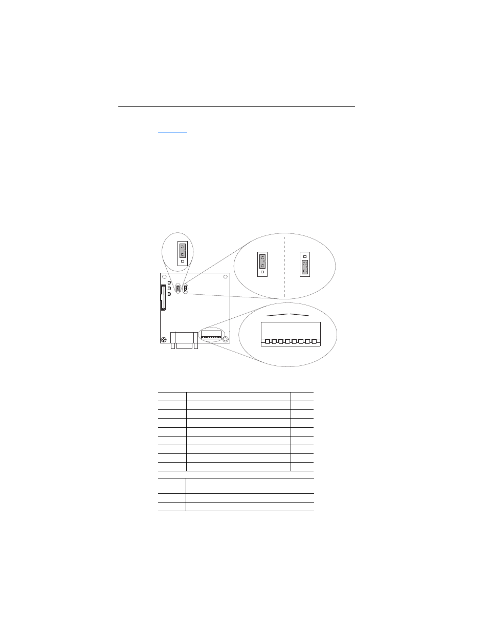
1. Set the adapter Node Address / Firmware Update switches (see
).
The Profibus Node Address/Firmware Update State is configurable
using an 8-bit DIP switch. The low seven bits set a node address and
the valid address allows binary coding of 1 through 125. A new node
address setting is recognized only when power is applied to the
adapter by power cycling the drive or after an adapter Reset Module
command. The MSB bit provides write access for the module flash
firmware update. In normal operating state, SW8 should be set to 1.
Figure 2.1 Setting the Node Address/Firmware Update Switches, Byte Swap
Jumper and Single/Multi-Drive Operation Jumper
Important: In normal operating state, SW8 should be set to 1.
Switches Description
Default
SW 1
Least Significant Bit (LSB) of Node Address
1
SW 2
Bit 1 of Node Address
1
SW 3
Bit 2 of Node Address
1
SW 4
Bit 3 of Node Address
1
SW 5
Bit 4 of Node Address
1
SW 6
Bit 5 of Node Address
1
SW 7
Most Significant Bit (MSB) of Node Address
1
SW 8
SW8 Firmware Update
1
SW 8
Setting
Description
0
Write Access Firmware Update
1
Normal Operating State
J2
Position A
J2
Position B
1X
5X
1X
5X
Single Mode
Operation
Multi-Drive Mode
Operation
2
1
8
3
4
5
6
7
NODE
ADDRESS SWITCHES
UP = OPEN = 1 = Off
DOWN = CLOSED = 0 = On
2
1
8
3
4
5
6
7
J3
SWAP
J4
J1
Series A adapter shown;
Series B adapter Jumper J2
and J3 locations are different