Seam-loc 24, System components – Metal Sales Seam-Loc 24 Installation User Manual
Page 21
© Metal Sales Manufacturing Corporation/ Subject to change without notice/ Effective Date 12/03
800.406.7387 (Corporate Office) • www.metalsales.us.com
20
SEAM-LOC 24
®
D
ESIGN
/ I
NSTALLATION
C
ONSIDERATIONS
(
CONT
.)
Steel roofing panels are subject to dimensional changes after installation due to exposure to varying temperatures. The greatest
influence is solar energy. Steel roofing absorbs various amounts of heat depending upon color, finish, angle of exposure, and
time of exposure.
The relationship of ambient temperature to building structural temperature must be considered when designing a Seam-Loc 24
roof system. The clips for the Seam-Loc 24 panels are designed for expansion and contraction of the panels in the longitudinal
direction. Lateral expansion and contraction is accommodated by the configuration of the panel cross section and causes
negligible panel movement.
When the total length of panel run exceeds the capability of the clips to accommodate the thermal movement, expansion joints
must be designed into the structure.
SYSTEM EXPANSION / CONTRACTION
The following information should be used to determine system components needed once insulation thickness has been selected.
Refer to pages 16-17 for appropriate fastener selections.
SELECTION OF SYSTEM COMPONENTS
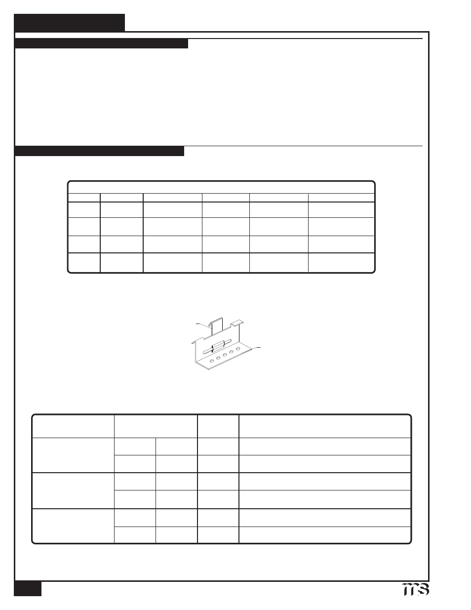
Seam-Loc 24 Panel Clips- The floating clips allow the roof surface (panels) to move independently of the roof substructure to
allow for thermal expansion and contraction. These clips are designed with a vertical tab that slides along the base section of
the clip. Clips are placed along the male leg of each panel prior to installing adjacent panels. Design wind uplift requirements
must be considered for proper clip spacing.
SEAM-LOC 24 PANEL CLIP
Vertical tab
Base
The following chart should be used to determine proper fasteners required for clip installation on the selected applications.
(See Product General Information pages 16-17 for other fasteners available.)
* Length of Dekfast will vary depending on the total thickness of the rigid insulation and metal (see page 17).
** Based on UL580. Subject to project loading requirements, closer clip spacing may be required. Contact your local Metal Sales
branch representative for more information (see pages 2 and 3).
2 FASTENERS
2 FASTENERS
2 FASTENERS
CLIP OVER RIGID
INSULATION /
METAL DECK
2 FASTENERS
2 FASTENERS
1
/
4
-14 x 1
1
/
2
" SELF DRILLER NW
1
/
4
-14 x 1
1
/
2
" SELF DRILLER NW
#10 X 1" PANCAKE HEAD WOOD
2 FASTENERS
# REQ.
TYPE OF FASTENER
APPLICATION
INSTALLATION
REQUIREMENTS
24 GAUGE
24 GAUGE
**CLIP
SPACING
5'-0" O.C.
BY DESIGN
5'-0" O.C.
STANDARD
#10 X 1" PANCAKE HEAD WOOD
22 GAUGE
BY DESIGN
CLIPS
OVER PURLINS
(16 GA. MIN)
CLIPS OVER
5
/
8
" WOOD DECK
DEKFAST #14*
24 GAUGE
4'-0" O.C.
22 GAUGE
4'-0" O.C.
DEKFAST #14*
STANDARD
STANDARD
STANDARD
STANDARD
STANDARD
22 GAUGE
RAKE ANGLE
2
5
/
8
" UTILITY
3
1
/
8
" LOW
3
5
/
8
" MID
SYSTEM COMPONENTS
SYSTEM
CLIP
EAVE PLATE
THERMAL BLOCK
INSULATION
UTILITY
LOW
MID
2
5
/
8
" UTILITY
3
1
/
8
" LOW
3
5
/
8
" MID
3
/
8
" LOW
1" MID
NONE REQUIRED
NONE REQUIRED
1"
1
/
2
" TO 4" BLANKET
4" TO 6" BLANKET
1
/
2
" TO 4" BLANKET
NONE REQUIRED
4
1
/
8
" HIGH
HIGH
4
1
/
8
" HIGH
1
3
/
8
" HIGH
1"
4" TO 6" BLANKET