Figure 8, Sensor band screw and alignment pins -14 – CiDRA SONARtrac PW VF-100 User Manual
Page 32
20831-01 Rev 05
Page 5-14
Position the passive sonar meter sensor band assembly on the pipe
with the polyimide film (amber colored) against the compliant layer.
Important: The attachment rails on an HD / segmented sensor band
must be installed on the top of a horizontal flowing pipe. Slide the
alignment pins on the attachment rail through their mating holes on
the opposite attachment rail.
If possible, orient the flow direction arrow on the sensor assembly with
the direction of flow within the pipe. Note: If this is not possible due to
installation constraints, e.g. access to sensor fasteners, install
opposite to flow direction. The transmitter must be re-configured for
“reverse flow” during its set up as detailed in the Transmitter Startup &
Operation Section of the manual.
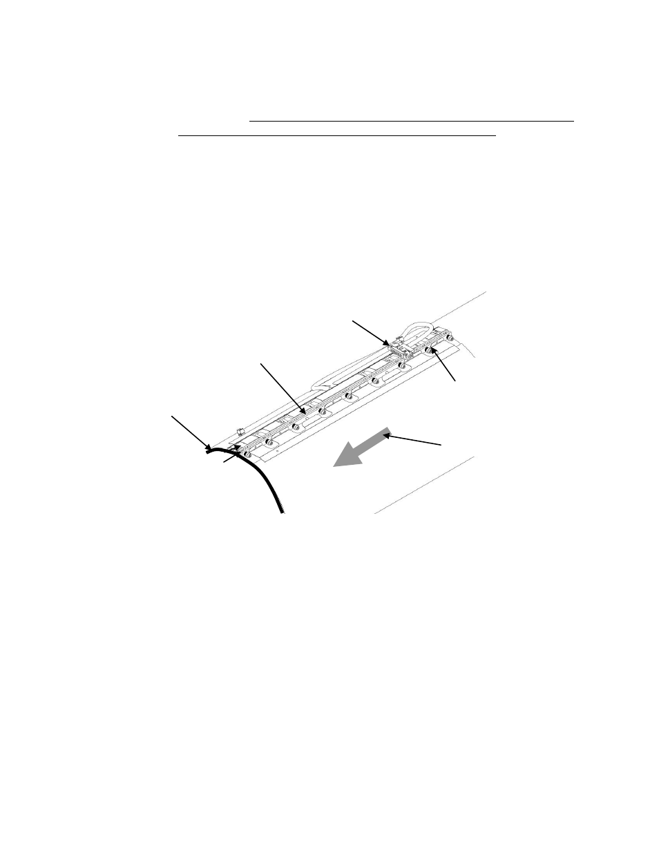
Figure 8
Sensor Band Screw and Alignment Pins
Carefully start threading the screws into their screw holes (avoid cross
threading) by using the hex driver until each screw is engaged about 2
turns. The following table provides guidance for selecting the proper
hex tool and spacer gauge.
Compliant sheet
(optional)
Sensor attachment screw
assembly (typical 9 places)
Alignment pins
(typical 2 places)
Flow direction arrow
Attachment rails
Sensor band shorting plug