2 externally powered 4-20ma loop configuration, 6 shd, 7 fieldbus – CiDRA SONARtrac PW VF-100 User Manual
Page 105: Externally powered 4-20ma loop configuration -11, Shd -11, Fieldbus -11, Figure 10, Externally powered 4, 20ma loop -11
20833-01 Rev 04
Page 7-11
7.3.5.2
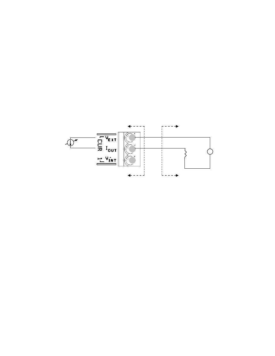
Externally Powered 4-20mA Loop Configuration
The connections for a 4-
20mA interface configured as “Externally
Powered” are shown below. The maximum value of V
EXT
should be
chosen such that the maximum applied voltage between V
EXT
and
local ground and I
OUT
and local ground shall be within the range of
+30V / -10V and current limited to 100mA. The maximum value of R
L
is determined by the following equation:
R
L Max
= (V
EXT
– 8.35) / (0.022)
For example, with V
EXT
= 24VDC:
R
L Max
= (24-8.35) / (0.022) = 711 Ohms
In the externally powered configuration the 4-20mA interface is
capacitively isolated from the rest of the transmitter electronics
provided that the applied voltages are within +30V / -30V.
Figure 10
Externally Powered 4
–20mA Loop
7.3.6
SHD
The three SHD (shield) terminals should only be used for grounding
shields of any output wiring such as connections to CUR 1 or CUR2.
These should not be used for the SENSOR 1 or 2 shields or for the
Sensor Head to Transmitter cable shield. Only one end of the shield
wire should be connected to eliminate shield currents.
7.3.7
Fieldbus
Optional Foundation Fieldbus communications are available on
passive sonar meter transmitters. Refer to document USE OF
FOUNDATION FIELDBUS
®
PROTOCOL WITH PASSIVE SONAR
METER TRANSMITTERS.
Plant control system
R
L
+
-
V
EXT
Transmitter
4-20mA
driver