Figure 18, Armored cable connector installed -23, Figure 19 – CiDRA SONARtrac PW VF-100 User Manual
Page 89: Armored cable installation -23
20832-01 Rev 05
Page 6-23
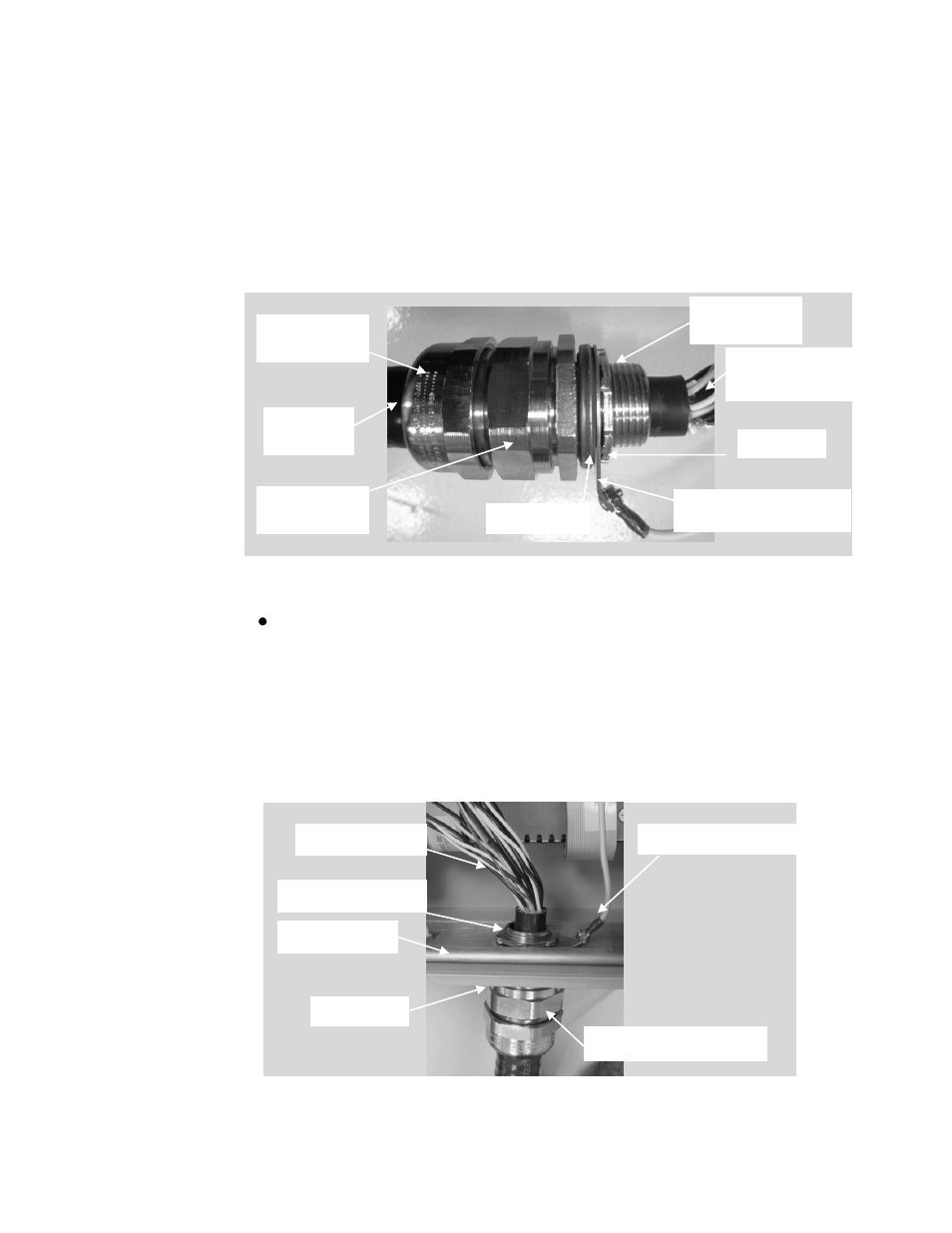
to the connector body and then final tighten 1-1/2 rotations using 1-
5/8” wrenches. Hand-tighten and then final tighten the
compression nut to the connector body 1 rotation using 1-
5/8”
wrenches. Cut and remove the conductor outer sheath about 3/4"
(19mm) from the end of the entry component. Remove foil outer
wrap and foil from each pair of conductors. As each pair is
unwrapped, twist each pair of conductors to keep them together as
pairs.
Figure 18
Armored Cable Connector Installed
Install the seal washer on the connector assembly entry
component. Insert the cable and entry component into the middle
hole in the transmitter box (stiffener plate previously installed.)
Install the ground ring wire assembly and lock nut. Secure the
connector assembly with the lock nut. Attach the ground wire from
the connector nut to any available SHD terminal on the Section #3
terminal block. Strip and install the individual connectors and drain
wire per non-armored cable installation instructions.
Figure 19
Armored Cable Installation
12 twisted pairs
plus drain wire
Connector
body
Compression
nut
Armored
cable
Seal washer
Ground ring wire
assembly
Lock nut
Entry
component
Connector body
Stiffener plate
Ground ring wire assembly
Conductor wires
Seal washer
Lock nut