1 transmitters with non-pluggable terminal blocks, Figure 8, Transmitter output terminals -14 – CiDRA SONARtrac PW VF-100 User Manual
Page 80: Table 1, List of transmitter signal outputs -14
20832-01 Rev 05
Page 6-14
6.3.4.3.1
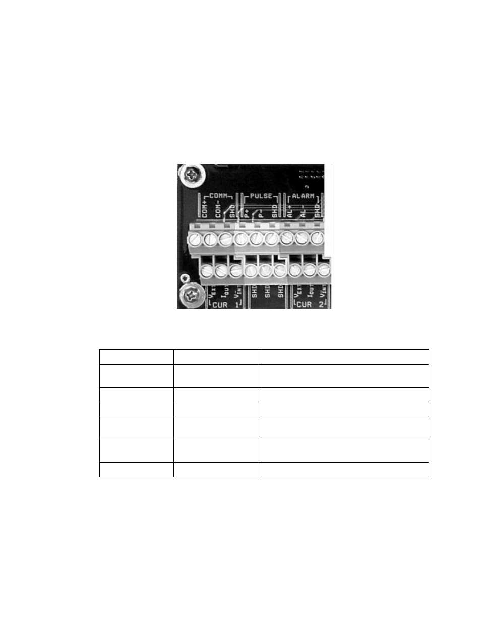
Transmitters With Non-Pluggable Terminal Blocks
The following figure provides a close-up of the transmitter output
terminals (Section #1 of the terminal board) with their functions listed
in the following table. These outputs can be connected as appropriate
to permit communications between the transmitter and other
equipment.
The recommended torque for the terminal screws is 4.4 to 5.3 lb
f
-inch
(0.5 to 0.6 Nm).
Figure 8
Transmitter Output Terminals
Terminal Label
Type
Comment
CUR 1
4-20mA #1 Output
Internal (self) or external (loop) powered,
HART communication capable
CUR 2
4-20mA #2 Output
Internal (self) or external (loop) powered
PULSE
Pulse output
Solid-state relay closure
ALARM
Alarm output
– High /
Low Output
Solid-state relay closure
COMM
RS-485 or 232 Output
MODBUS communications on units with this
option
SHD
---
Shield Connections
Table 1
List of Transmitter Signal Outputs