3 transmitter housing cable entry, Transmitter housing cable entry -10, Figure 5 – CiDRA SONARtrac PW VF-100 User Manual
Page 76: Transmitter housing cable gland holes -10, Warning
20832-01 Rev 05
Page 6-10
6.3.3
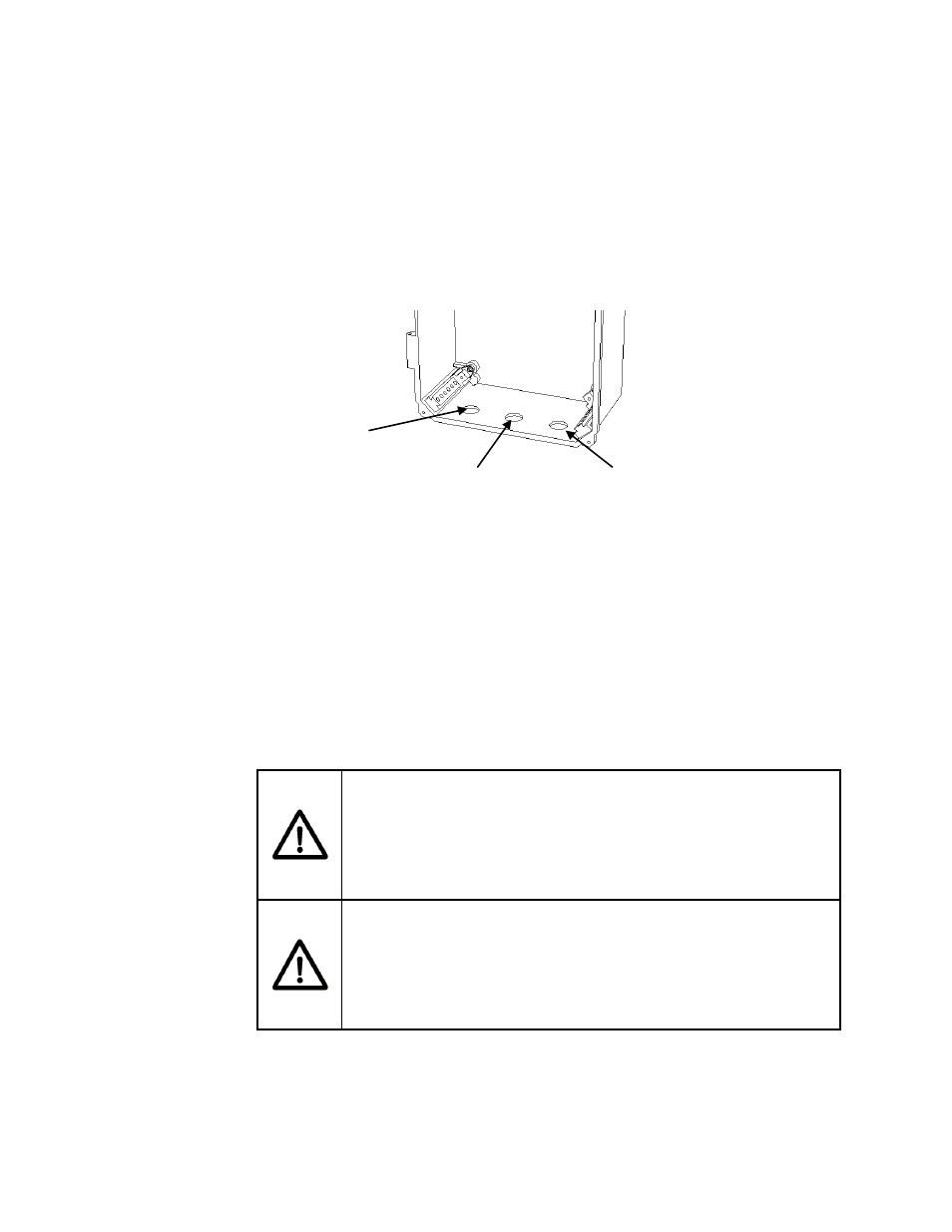
Transmitter Housing Cable Entry
Power, sensor signal, and input /output signal cables enter the
transmitter housing through cable glands. The cable glands also
provide strain relief for the cables. Always ensure they are fully
tightened. The following figure illustrates where each of the cable
glands are installed.
Figure 5
Transmitter Housing Cable Gland Holes
Note: For Ordinary Locations as well as for Hazardous Locations the
four cover sealing screws on the transmitter cover must be securely
tightened in order to ensure a proper seal, all cable entries require
cable glands, and any unused cable gland holes must be sealed with
the gasketed hole plugs that came with the Transmitter. On
transmitters installed in Class I Division 2 areas, cable glands rated for
NEMA 4X (minimum rating) must be used. Similarly, for ATEX Zone
2, cable glands must be ATEX-certified and at least IP55. See
SONAR PROCESS MONITORING SYSTEM SUPPLEMENT FOR
ATEX ZONE 2 SAFETY for additional info and requirements.
WARNING
Transmitter cover screws must be securely tightened and NEMA
4X rated cable glands must be used in Class I Division 2
applications. Failure to do so is a violation of Class I Division 2
certification.
WARNING
Transmitter cover screws must be securely tightened and ATEX
cable glands with IP55 rating must be used in ATEX Class I Zone
2 applications. Failure to do so is a violation of ATEX Class I
Zone 2 certification.
User I/O cable
gland hole
Sensor head to transmitter
cable gland hole
Power cable gland hole