Figure 15, Ip-65 rated connector -21, Table 4 – CiDRA SONARtrac PW VF-100 User Manual
Page 87
20832-01 Rev 05
Page 6-21
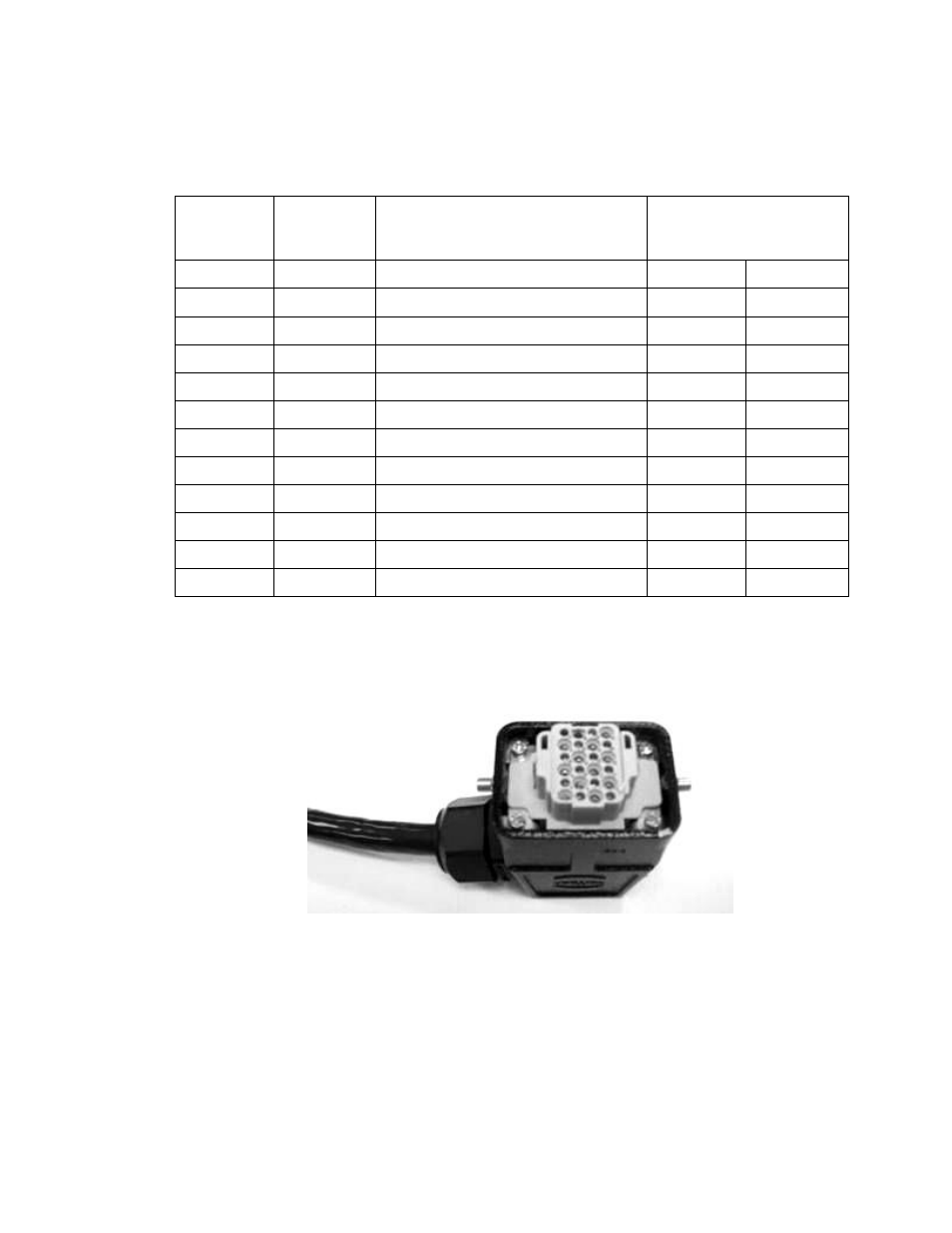
The following table lists the cable connector pin-out for cables
equipped with the IP-65 rated connector (Figure 15).
Table 4
Sensor to Transmitter Cable Terminal Connections IP-65 Connector
Figure 15
IP-65 Rated Connector
Wire Pair # Transmitter
Terminal #
Function
SENSOR HEAD
CONNECTOR PIN
NUMBER
1 Wht/Blk
1
Sensor #1 Input
15 - Blk
16 - Wht
2 Wht/Blk
2
Sensor #2 Input
13 - Blk
14 - Wht
3 Wht/Blk
3
Sensor #3 Input
11 - Blk
12 - Wht
4 Wht/Blk
4
Sensor #4 Input
9 - Blk
10 - Wht
5 Wht/Blk
5
Sensor #5 Input
7 - Blk
8 - Wht
6 Wht/Blk
6
Sensor #6 Input
5 - Blk
6 - Wht
7 Wht/Blk
7
Sensor #7 Input
3 - Blk
4 - Wht
8 Wht/Blk
8
Sensor #8 Input
1 - Blk
2 - Wht
9 Wht/Blk
9
Spare
– unused
---
---
10 Wht/Blk
10
Wht
– RS 485 Hi / Blk – RS485 Low
23 - Wht
24 - Blk
11 Wht/Blk
11
Wht
– ‘-12 V’ / Blk – Gnd
19 - Wht
20 - Blk
12 Wht/Blk
12
Wht
– ‘+12 V’ / Blk – Gnd
17 - Wht
18 - Blk