Figure 9, Sensor band screw tightening sequence -15, Table 5 – CiDRA SONARtrac PW VF-100 User Manual
Page 33: Gauge block and screw size -15
20831-01 Rev 05
Page 5-15
1
2
3
4
5
6
7
8
9
Sensor band assembly
Table 5
Gauge Block and Screw Size
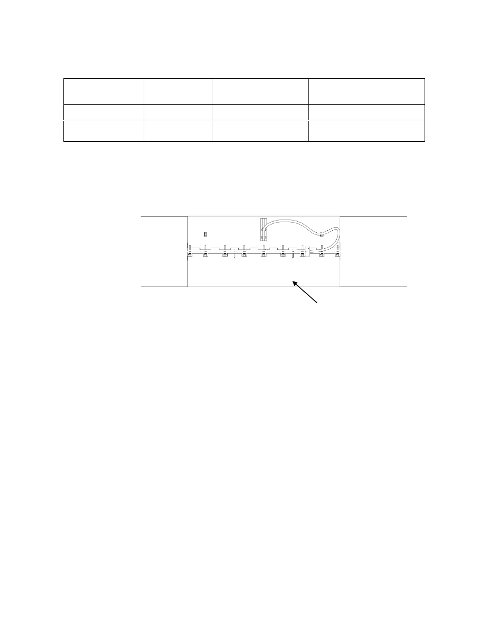
Start with the center most screw and tighten screws, alternating from
side to side, 3 - 4 turns at a time. Refer to the following figure for the
screw tightening sequence. Note: Repeat the tightening sequence
only until the Belleville disc springs on the screws begin to compress.
Figure 9
Sensor Band Screw Tightening Sequence
The sensor screw stack up assembly is illustrated on the following
page.
Sensor Band P/N
Spacer Gauge
P/N
Socket Head Screw
Hex Size (inch)
Band Attachment Rail
Size (Ref)
20669- ALL SIZES
20143-01
7/64
1/8 x 3/8
20690- ALL SIZES
20143-04
5/32
1/4 x 1/2
This manual is related to the following products: