Figure 10, Sensor band screw assembly -16, Figure 11 – CiDRA SONARtrac PW VF-100 User Manual
Page 34: Sensor band spacer gauge -16
20831-01 Rev 05
Page 5-16
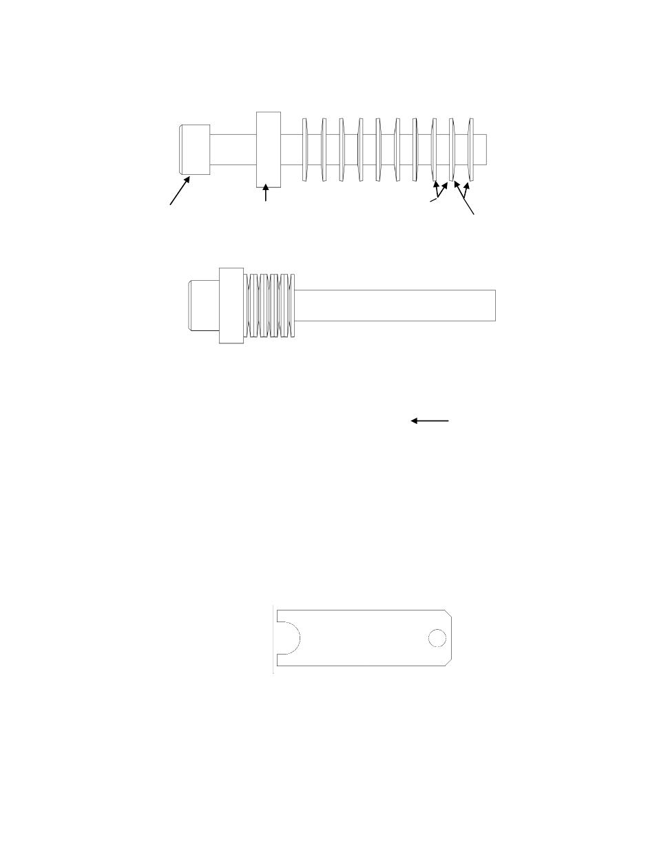
Figure 10 Sensor Band Screw Assembly
Further tightening of the sensor band screws is made while using the
sensor band spacer gauge (shown below) furnished with the sensor
band. The spacer gauge is used to set the compression on the
Belleville washers referred to above. Refer to Table 4 for proper
spacer gauge selection.
Figure 11 Sensor Band Spacer Gauge
Using the sensor band screw tightening sequence shown in Figure 9,
insert the sensor band spacer gauge over the Belleville washers on
the middle sensor screw assembly and tighten it such that it is snug
but the spacer gauge can still be removed. The following figure
illustrates use of the sensor band screw spacer gauge.
Sensor screw
Sensor screw spacer
(may be integral to
screw head)
Sensor Belleville washers
convex side
Sensor Belleville washers
concave side
Belleville washers and spacer
compressed against screw head
) ( ) ( ) ( ) ( ) ( ) ( ) (
Note: Sensor bands 18” and
larger have 14 Belleville washers
per screw arranged as shown
Note: 10 Belleville Washers on 2-16” bands