Table 12 – CiDRA SONARtrac PW VF-100 User Manual
Page 135
20833-01 Rev 04
Page 7-41
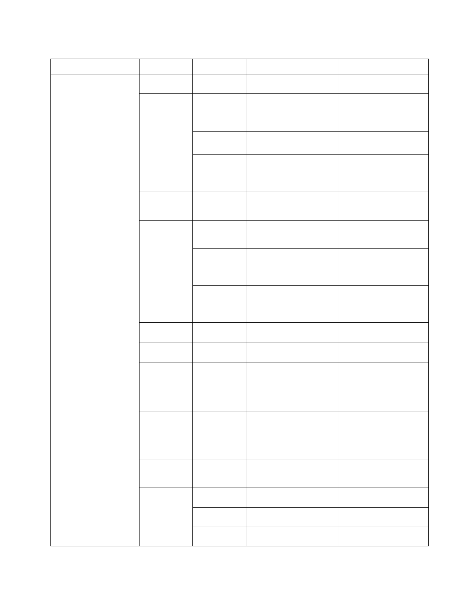
Table 12
VF/GVF Transmitter Menu Tree Software Release 04.02.XX
Level 1
Level 2
Level 3
Range
Description
Basic Config
Sensor
Serial #
0000000
Serial number of sensor
band
Pipe Size
ID/Wall
ID: 0.1- 100 in (2.54-
2540mm)
Wall 0
– 100 in (0 to
2540 mm)
Pipe inner diameter and
wall thickness
Size/Sched
2 to 36" size;
schedule
Pipe size & schedule
OD/Wall
OD: 0.1- 300 in (2.54-
7260mm)
Wall 0
– 100 in (0 to
2540 mm)
Pipe outer diameter and
wall thickness
Pipe Material
SST, CS, PVC, Custom
Enters the pipe
modulus, kilo-Pascal
(kPa)
Fluid
Properties
Spec Gravity
0 - 999999
Enters the specific
gravity; default water at
25 °C and 14.7 psia
SOS (ft/s)
0 - 999999
Sound speed in media
of interest; ft/sec;
default water at 25 °C
and 14.7 psia
Viscosity
0.0000 e-38 to
9.9999 e+38
Enters the liquid
viscosity in Pa-sec;
default water at 25 °C
and 14.7 psia
Pressure
+/- 0-999999
Process pressure; PSIg,
Barg, kPag
Temperature
-999 to +999C
-1766 to 1830F
Process temperature;
°C or F
Pressure Sel
Fixed, Sensor #1 or #2,
Protocol
Allows for selecting a
fixed pressure input or
using the inputs of
sensor #1 or #2 or using
Modbus input
Temperature
Sel
Fixed, Sensor #1 or #2
Allows for selecting a
fixed temperature input
or using the inputs of
sensor #1 or #2 or using
Modbus input
Altitude
-50,000 to +50,000
Process pipe altitude
above / below sea level;
feet or meter
Calibration
C0 term
0.0000 e-38 to
9.9999 e+38
First term coefficient
C1 term
0.0000 e-38 to
9.9999 e+38
Second term coefficient
C2 term
0.0000 e-38 to
9.9999 e+38
Third term coefficient