Figure 38, Splice protector plate installation -35, Figure 39 – CiDRA SONARtrac PW VF-100 User Manual
Page 53: Band-it, Model c00169 tool use -35
20831-01 Rev 05
Page 5-35
loose enough so the band will still slide through the buckle. Repeat on
the opposite end of the cover.
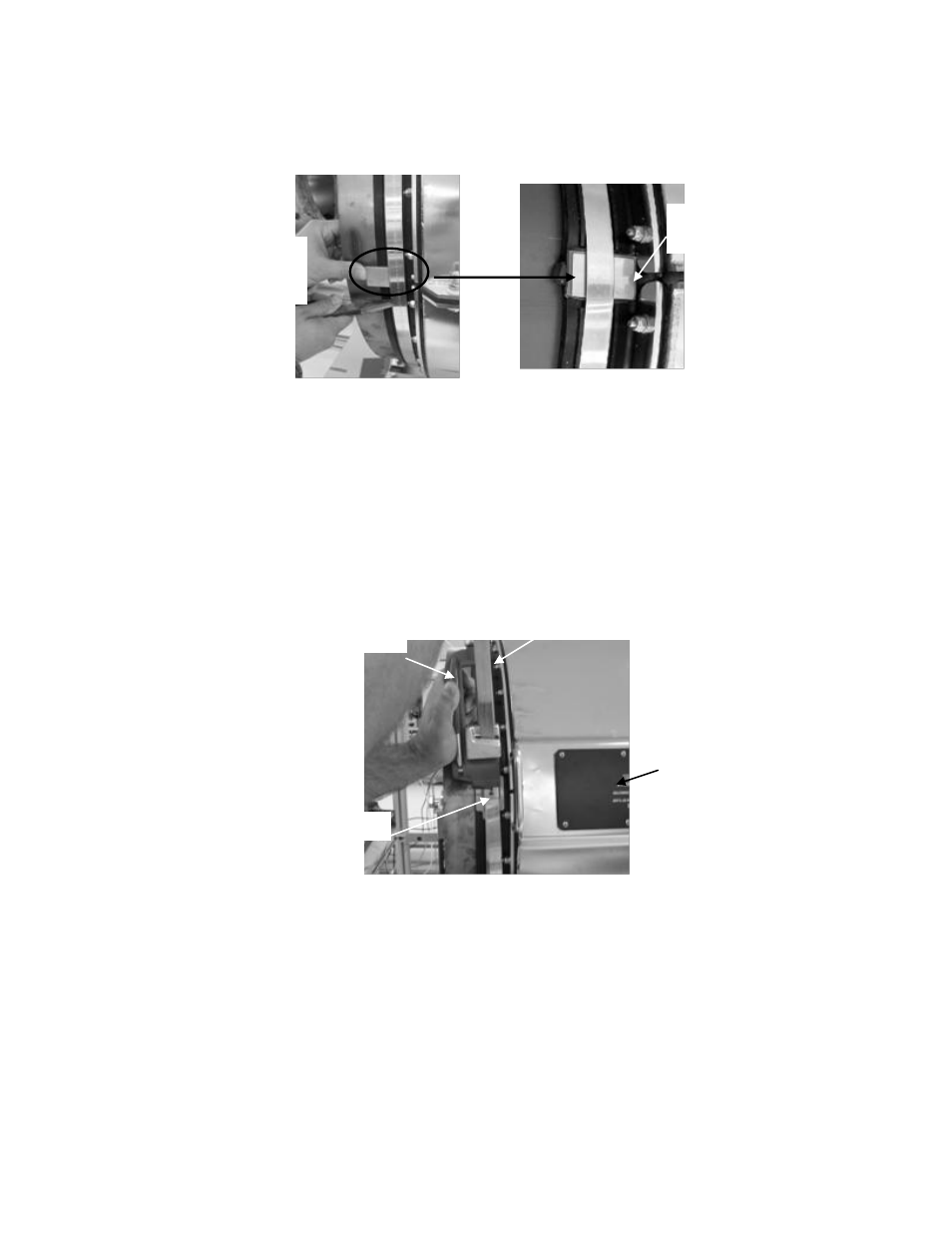
Figure 38 Splice Protector Plate Installation
Install the BAND-IT
®
Model C00169
tensioning tool by inserting the
band through the cutter bar and slide lock.
Note: This tool is asymmetric. The tool will pull in opposite directions
when installed on opposite ends of the cover. The cutter handle
(positioned either up or down) on the Model C00169 is located
outboard with respect to the cover end, when the tool is properly
installed. The following figure illustrates proper installation of the tool.
Figure 39 BAND-IT
®
Model C00169 Tool Use
Verify the band is still aligned within the grooves on the boot gasket
and over the first wrap of the band, and the band buckle is positioned
over the gasket protector plate.
Tension the band until the resistance on the tool handle is constant
(i.e. the band does not slide easily through the buckle). The boot
gasket should be tight against the process pipe under the gasket
protector plate. Verify the band buckle and splice protector plates are
still in place.
Tensioning tool cutter
handle outboard of cover
Excess band material
Band buckle
Sensor cover
Lift band with
needle nose pliers
or screw driver
Splice protector plate
centered on gasket splice