Figure 1, Sensor band screw and alignment pins -9, Table 4 – CiDRA SONARtrac PW VF-100 User Manual
Page 27: Gauge block and screw size -9
20831-01 Rev 05
Page 5-9
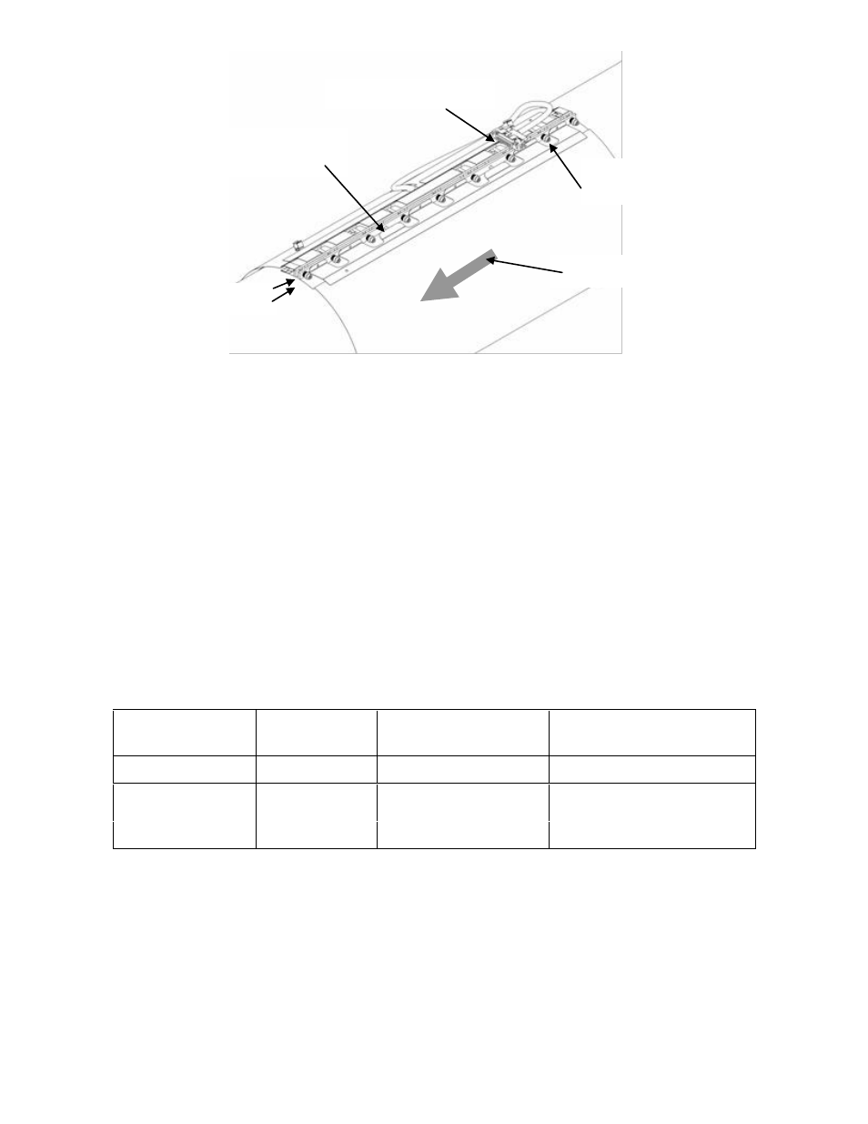
Figure 1
Sensor Band Screw and Alignment Pins
Wrap the sensor band around the pipe and slide the alignment pins on
the attachment rail through their mating holes on the opposite
attachment rail. If the process pipe has a welded seam, align the gap
between the sensor attachment rails along the pipe weld seam. Final
positioning can be made after the sensor screws have been started.
Note: When installing the sensor band keep in mind the requirement
for transmitter connector socket assembly orientation as described in
Section 5.7. If necessary, due to cover installation constraints, wrap
the sensor band over the weld seam.
Carefully start threading the screws into their screw holes (avoid cross
threading) by using the hex driver until each screw is engaged about 2
turns. Once all screws are engaged make final positioning of the
sensor assembly with respect to pipe weld seam or desired orientation
on the pipe. The following table provides guidance for selecting the
proper hex tool and spacer gauge.
Table 4
Gauge Block and Screw Size
Sensor Band P/N
Spacer Gauge
P/N
Socket Head Screw
Hex Size (inch)
Band Attachment Rail
Size (Ref)
20380- ALL SIZES
20143-01
7/64
1/8 x 3/8
20409- ALL SIZES
20143-02
7/64
1/8 x 3/8
20686- ALL SIZES
20143-04
5/32
1/4 x 1/2
Sensor attachment screw
assembly (typical 9 places)
Alignment pins
(typical 2 places)
Flow direction arrow
Attachment rails
Sensor band shorting plug