3 alarm, Alarm -8, Figure 5 – CiDRA SONARtrac PW VF-100 User Manual
Page 102: Pulse switch closure -8, Figure 6, Alarm switch closure -8
20833-01 Rev 04
Page 7-8
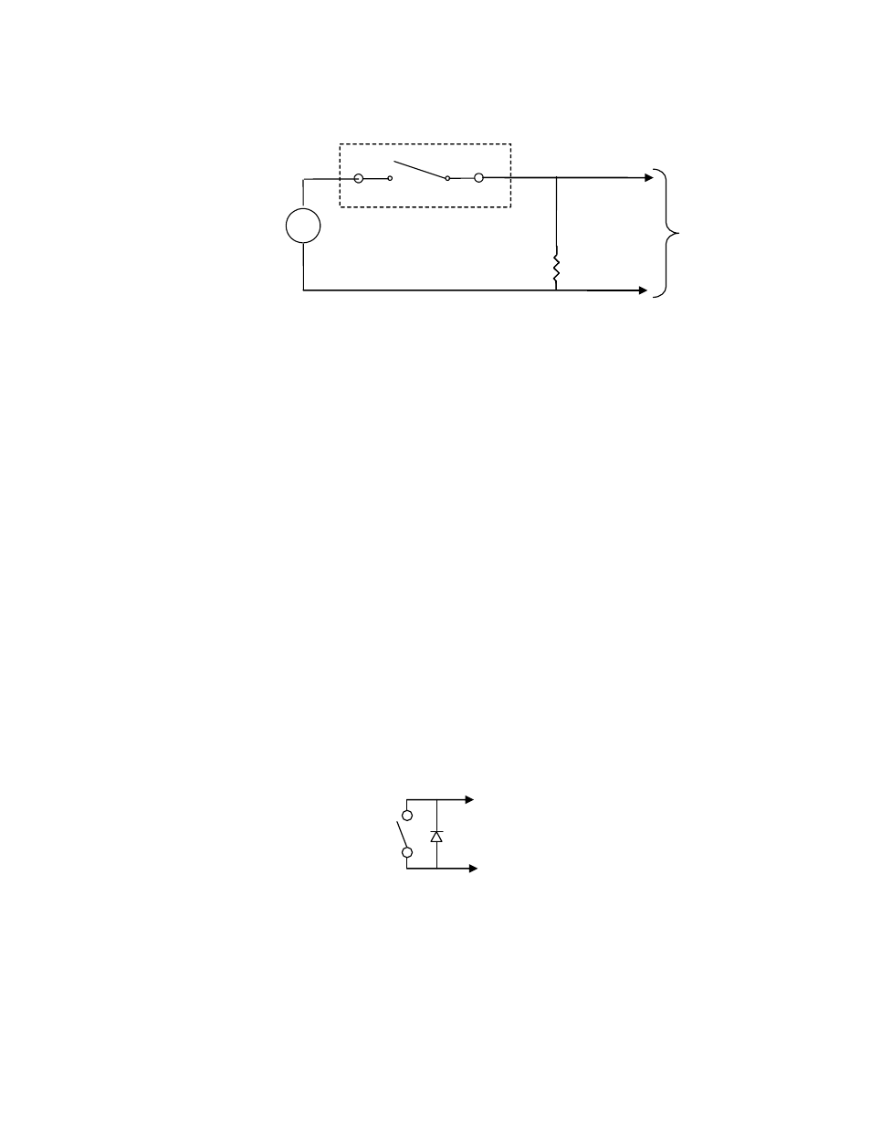
Figure 5
Pulse Switch Closure
For sizing R
1
refer to the following example.
Power Supply = 24V
Choose a value for R
1
so as to not exceed 100mA
R
1
= 24V / 100mA = 240
Ω
Therefore, R
1
should be sized to be greater than
240Ω so the current does not exceed 100mA
Note: Recommended minimum swing pulse is 1 msec. At the 0.5
msec pulse width setting, the voltage across the solid-state relay will
be approximately 50% of power supply voltage.
7.3.3
ALARM
The alarm output consists of an electrically isolated switch closure
occurs between AL+ and AL- whenever the limits specified in the
transmitter setup for Alarm are met. These limits can be changed or
disabled through the local keypad and display. The maximum applied
voltage between AL+ and local ground and AL- and local ground shall
be within the range of +30V / -10V. The load current shall be a
maximum of 100mA.
The ‘EXIT’ key is used to clear alarms while in the Operational Mode.
Figure 6
Alarm Switch Closure
AL+ (HI)
AL- (LOW)
To
Counter
Inputs
R1
Out-
Out+
P-
P+
-
+
Power
Supply