Installing a bigiron rx-4 switch, Preparing the installation site, Cabling infrastructure – Brocade BigIron RX Series Hardware Reference Manual User Manual
Page 36
24
Brocade BigIron RX Series Hardware Installation Guide
53-1002483-03
Installing a BigIron RX-4 switch
2
CAUTION
For the DC input circuit to the system, make sure there is a UL-Listed 30 amp circuit breaker,
minimum -48Vdc, double pole, on the input to the terminal block. The input wiring for connection
to the product should be Listed copper wire, 8 AWG, marked VW-1, and rated minimum 9
o
C.
Installing a BigIron RX-4 switch
This section describes the steps you will perform to install a BigIron RX-4 switch:
•
“Preparing the installation site”
•
“Unpacking a BigIron RX-4 switch”
•
“Chassis lifting guidelines for BigIron RX-4 switches”
•
“Installing a BigIron RX-4 chassis in a rack”
•
“Installing BigIron RX-4 modules”
•
“Installing power supplies in a BigIron RX-4 chassis”
•
“Connecting AC power to a BigIron RX-4 chassis”
•
“Connecting DC power to a BigIron RX-4 chassis”
•
Preparing the installation site
Cabling infrastructure
Ensure that the proper cabling is installed in the site.
For information on cabling, refer to
“Installing power supplies in a BigIron RX-4 chassis”
“Attaching a management station”
on page 54, and
“Connecting a BigIron RX Series
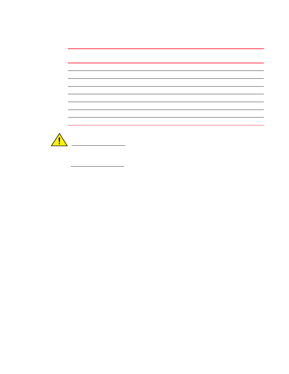
TABLE 9
The American Wire Gauge (AWG) guidelines
AWG
Ohms per 100 feet
Maximum Amps for chassis wiring
Maximum Amps for power
transmission
5
0.3133
118
47
6
0.3951
101
37
7
0.4982
89
30
8
0.6282
73
24
9
0.7921
64
19
10
0.9989
55
15
11
1.26
47
12
12
1.588
41
9.3