Management modules – Brocade BigIron RX Series Hardware Reference Manual User Manual
Page 19
Brocade BigIron RX Series Hardware Installation Guide
7
53-1002483-03
Hardware features
1
show the BigIron RX Series chassis and the slots into which you
install the various modules. You must install the primary power supplies and the redundant power
supplies as described in the figures.
also show an electrostatic discharge (ESD) connector, into which
you can plug an ESD wrist strap to ground yourself while handling and installing modules.
DANGER
For safety reasons, the ESD wrist strap should contain a 1 meg ohm series resistor.
The BigIron RX-16 chassis versions also include a grounding lug connector, located on the rear
panel (left side). The BigIron RX-4 and BigIron RX-8 have two threaded holes on the right side of the
chassis to accommodate the addition of a ground lug connector.
Management modules
The management module controls the BigIron RX Series hardware components, runs the
networking protocols, and provides the Real Time Operating System (RTOS).
Each BigIron RX Series chassis requires one management module and can accept a second one for
redundancy. A redundant management module works along with the active management module.
If the active module becomes unavailable, the redundant management module automatically
takes over the system operation, minimizing system downtime.
You can install management modules in dedicated slots marked M1 and M2. By default, the
system considers the module installed in the slot marked M1 to be the active management
module.
NOTE
BigIron RX-4, The BigIron RX Series management module is dedicated, which means that you must
install it in the BigIron RX Series chassis only. If you attempt to install the BigIron RX Series
management module in another Brocade chassis or a management module intended for another
Brocade chassis in the BigIron RX Series chassis, the chassis and module will not function properly..
A management module is hot swappable, which allows you to remove and replace it without
powering down the system.
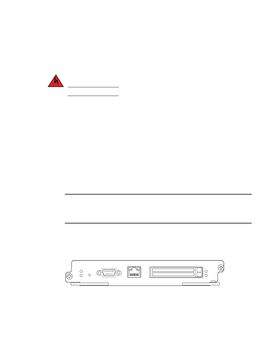
shows the management module’s front panel.
FIGURE 4
Management module front panel
The front panel includes the following control features:
•
Two PCMCIA slots
•
A Console port
•
A 10/100/1000 Ethernet port
•
Six LEDs
Pwr
Active
10/100/1000
Port 1
Port 2
Console
RX-BI-MR