2 i2c bus dynamics, Figure 2-9. i2c start and stop conditions -11, C bus dynamics – Cirrus Logic CS4970x4 User Manual
Page 57: Scp1_clk scp1_sda start scp1_clk scp1_sda stop
2-11
Copyright 2013 Cirrus Logic, Inc.
DS810UM6
I2C Port
CS4953x4/CS4970x4 System Designer’s Guide
2.5.2 I
2
C Bus Dynamics
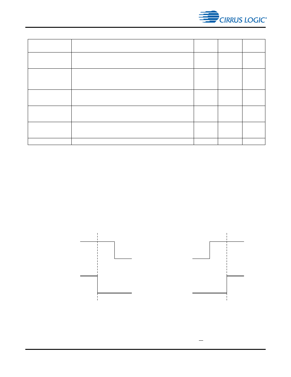
The Start condition for an I
2
C transaction is defined as the first falling edge on the SCP1_SDA line while
SCP1_CLK is high. An I
2
C Stop condition is defined as the first rising edge on the SCP1_SDA line while
SCP1_CLK is high. Hence for valid data transfer, SCP1_SDA must remain stable during the high period of
the clock pulse. Start and Stop conditions are always generated by the Master. The bus is considered to
be busy after the Start condition. The bus is considered to be free again following the Stop condition. The
bus stays busy if a repeated Start condition is generated instead of a Stop condition. In this respect, the
Start and repeated Start conditions are functionally identical.
Figure 2-9. I
2
C Start and Stop Conditions
The number of bytes that can be transmitted per transfer is unrestricted. Data is transferred with the most-
significant bit (MSB) first. The first byte is an address byte that is always sent by the Master after a Start or
repeated Start condition. This byte must be a 7-bit I
2
C Slave address + R/W bit. The 7-bit I
2
C address for
SCP1_BSY
Serial Control Port 1 Input Busy, Output, Active Low
This pin is driven low when the control port’s receive buffer is full.
Internal Buffer is 4 bytes (1 DSP Word) deep.
102
128
Open Drain
SCP2_CS
SPI Chip Select, Active Low
In serial SPI Slave mode, this pin is used as the active-low chip-select
input signal. In SPI serial Master mode, if this pin is driven low by
another Master device on the bus, it will cause a mode fault to occur.
104
7
Input
SCP2_CLK
SPI Control Port Bit Clock
In Master mode, this pin serves as the serial control clock output. In
serial Slave mode, this pin serves as the serial control clock input.
103
1
I/O
SCP2_MISO
SPI Mode Master Data Input/Slave Data Output
In SPI Slave mode this pin serves as the data input. In SPI Master mode
this pin serves as the data output.
105
2
I/O
SCP2_MOSI
SPI Mode Master Data Output/Slave Data Input
SCP2_MOSI in SPI Slave mode this pin serves an the data input, in SPI
Master mode this pin serves as the data output.
106
3
I/O
EE_CS
Master Mode SPI Flash Chip Select, Active Low
25
14
Output
Table 2-2. Serial Control Port 1 I
2
C Signals (Continued)
Pin Name
Pin Description
LQFP-144
Pin #
LQFP-128
Pin #
Pin
Type
SCP1_CLK
SCP1_SDA
Start
SCP1_CLK
SCP1_SDA
Stop