AMD SB600 User Manual
Page 189
©2008 Advanced Micro Devices, Inc.
IDE Controller (Device 20, Function 1)
AMD SB600 Register Reference Manual
Proprietary
Page 189
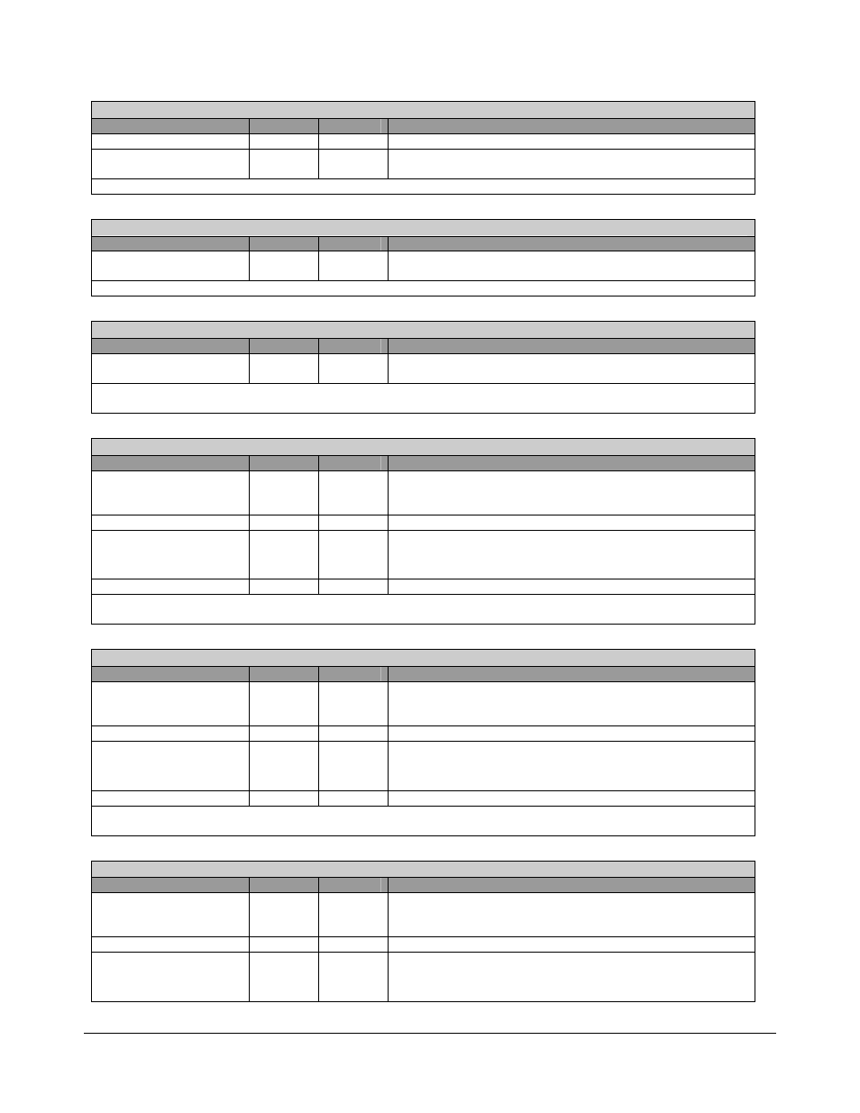
Master Latency Timer - RW - 8 bits - [PCI_Reg:0Dh]
Field Name
Bits
Default
Description
Reserved
2:0
0h
They are not used and wired to 0.
Master Latency Timer
7:3
00h
Master Latency Timer. This number represents the guaranteed
time slice allotted to IDE host controller for burst transactions.
Master Latency Timer: This register specifies the value of Latency Timer in units of PCICLKs.
Header Type - R - 8 bits - [PCI_Reg:0Eh]
Field Name
Bits
Default
Description
Header Type
7:0
00h
Header Type. Since the IDE host controller is a single-function
device, this register contains a value of 00h.
Header Type Register: This register identifies the IDE controller module as a single function device.
BIST Mode Type - R - 8 bits - [PCI_Reg:0Fh]
Field Name
Bits
Default
Description
Built-in-Self Test Mode
7:0
00h
Built-in-Self Test modes. Since the IDE host controller does
not support BIST modes, this register is always read as 00.
BIST Mode Type Register: This register is used for control and status for Built-in-Self test. The IDE host controller
has no BIST modes
Base Address 0 - RW - 32 bits - [PCI_Reg:10h]
Field Name
Bits
Default
Description
Resource Type Indicator
0
1b
RTE (Resource Type Indicator). This bit is wired to 1 to
indicate that the base address field in this register maps to I/O
space.
Reserved
2:1
00b
Reserved. Always read as 0’s.
Primary IDE CS0 Base
Address
15:3 0000h
Base Address for Primary IDE Bus CS0. This
register is
used for native mode only. Base Address 0 is not used
in compatibility mode.
Reserved
31:16
0000h
Reserved. Always read as 0’s.
Base Address 0 Register (Primary CS0): This register identifies the base address of a contiguous IO space of
command register block for the primary channel.
Base Address 1 - RW - 32 bits - [PCI_Reg:14h]
Field Name
Bits
Default
Description
Resource Type Indicator
0
1b
RTE (Resource Type Indicator). This bit is wired to 1 to
indicate that the base address field in this register maps to I/O
space.
Reserved
1
0b
Reserved. Always read as 0’s.
Primary IDE CS1 Base
Address
15:2 0000h
Base Address for Primary IDE Bus CS1. This
register is
used for native mode only. Base Address 1 is not used
in compatibility mode.
Reserved
31:16
0000h
Reserved. Always read as 0’s.
Base Address 1 Register (Primary CS1): This register identifies the base address of a contiguous IO space of
command register block for the primary channel.
Base Address 2 - RW - 32 bits - [PCI_Reg:18h]
Field Name
Bits
Default
Description
Resource Type Indicator
0
1b
RTE (Resource Type Indicator). This bit is wired to 1 to
indicate that the base address field in this register maps to I/O
space.
Reserved
2:1
00b
Reserved. Always read as 0’s.
Secondary IDE CS0
Base Address
15:3 0000h
Base Address for Secondary IDE Bus CS0. This
register is
used for native mode only. Base Address 2 is not used
in compatibility mode.