Operating principle, 1 principle of magnetic flowmeter operation, Operating principle -1 – Yokogawa ADMAG CA User Manual
Page 88: Principle of magnetic flowmeter operation -1
IM 1E8B0-01E
11-1
11. OPERATING PRINCIPLE
11. OPERATING PRINCIPLE
11.1 Principle of Magnetic Flowmeter Operation
The operating principle of the magnetic flowmeter is based on the law of electromag-
netic induction which states that when a conductor moves in a magnetic field, in the
direction perpendicular to the magnetic field, an electromotive force is induced perpen-
dicular to the direction of the conductor movement and to the direction of the magnetic
field. The value of the electromotive force is proportional to the conductor velocity and
magnetic flux density.
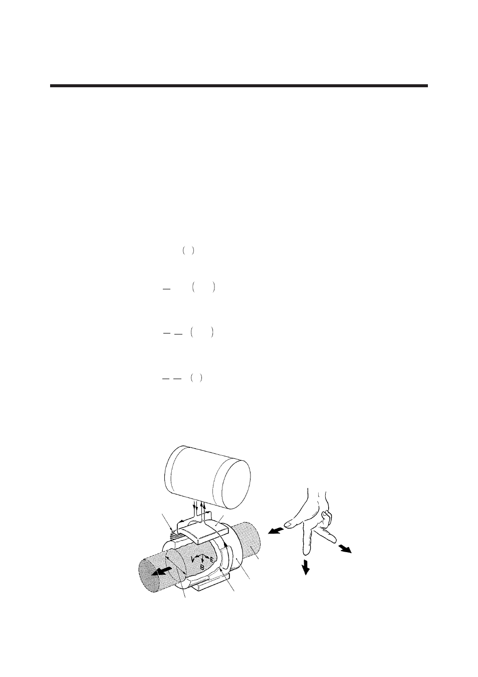
In Figure 11.1, when a conductive fluid flows at an average velocity of V (m/s) through
a pipe whose inner diameter is D (m), in which a magnetic field of uniform flux density
B (tesla) exists, an electromotive force E (volts) is induced perpendicular to the direction
of the magnetic field and to the flow.
E=D
⋅
V
⋅
B V
................. (1)
The volumetric flowrate Q is obtained from the following equation.
Q=
π
4
⋅
D
2
⋅
V m
3
/s
...... (2)
From equations (1) and (2), the next equation is obtained.
Q=
π
4
⋅
D
Β
⋅Ε
m
3
/s
....... (3)
Therefore, the electromotive force E is expressed as shown below.
E=
π
4
⋅
B
D
⋅
Q V
............. (4)
If B is constant, then Q will be proportional to E from equation (3).
The magnetic flow converter amplifies and converts this electromotive force E to a
standard signal of 4 to 20 mA or a pulse signal.
Flow Converter
Coil
Iron core
Flow velocity V
Magetic field (flux density B)
Electromotive force E
Liquid
Flowmeter tube
Electrodes
Pipe inner diameter D
Figure 11.1 Operating Principle