Installation, 1 piping design precautions, Installation -1 – Yokogawa ADMAG CA User Manual
Page 10: Piping design precautions -1, Warning important important important important
4.INSTALLATION
IM 1E8B0-01E
4-1
4. INSTALLATION
This instrument must be installed by expert engineer or skilled personnel.
The procedures described in this chapter are not permitted for operators.
4.1 Piping Design Precautions
Please design the correct piping referring to the followings to prevent
damage for flowmeter and to keep correct measuring.
(1) Location
Please install the flowmeter to the location where it is not exposed to direct
sunlight and ambient temperature is -20 to +50˚C (-4 to 122˚F) .
(2) Noise Rejection
• The instrument should be installed away from large electrical motors,
transformers and other power sources in order to avoid interference with
the measurement.
• In case several capacitance Magnetic Flowmeters are installed, please
install them 1 m (40 in) or more apart.
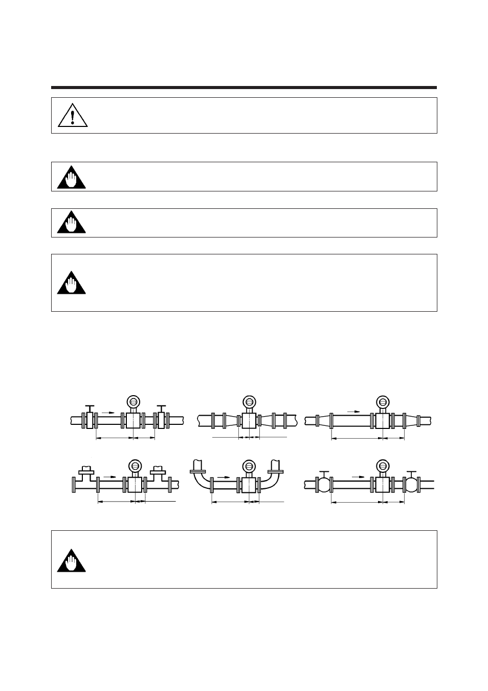
(3) Length of Straight Run
To keep accurate measuring, JIS B7554 “Electro Magnetic Flowmeters” explains about
upstream piping condition of Magnetic Flowmeters.
We recommend to our customers about the piping conditions shown in Figure 4.1.1
based on JIS B7554 and our piping condition test data.
D:Internal diameter of flowmeter
Gate valve fully open
Reducer pipe
90 degrees bent
Various type of valves
5D or more
5D or more
2D or more
Expander pipe
10D or more
2D or more
10D or more
2D or more
Do not care to 0D
Do not care to 0D
5D or more
Do not care to 0D
Tee
Figure 4.1.1
Minimum Length of Required Straight Run
In the application for pure water, pure alcohol and other fluids which have
low conductivity with low viscosity, we recommend the upper stream length
of straight run of magmeter be 20D ( where D denotes size of flow tube) or
more. Please be careful that gasket material dose not protrude in pipe
inner surface.
Notes : 1. Nothing must be inserted or installed in the metering pipe that may interfere with the magnetic
field, induced signal voltages, and flow velocity distribution.
2. These straight runs may not be required on the downstream side of the flowmeter. However, if
the downstream valve or other fittings cause channeling on the upstream side, provide a straight
run of 2 D to 3 D on the downstream side.
WARNING
IMPORTANT
IMPORTANT
IMPORTANT
IMPORTANT