3 pulse output (refer to 6.3.1), Pulse output (refer to 6.3.1) -9 – Yokogawa ADMAG CA User Manual
Page 59
IM 1E8B0-01E
7-9
7. OPERATION VIA BRAIN TERMINAL
7.2.3
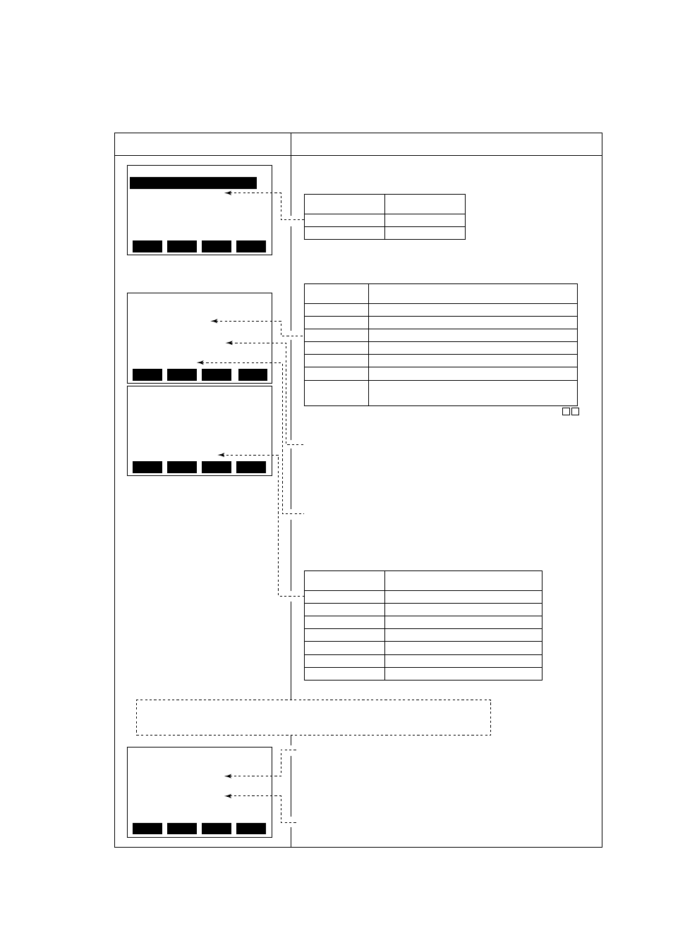
Pulse Output (Refer to 6.3.1)
Example setting : 10 liter output per pulse in a flow rate span of
ٗٗٗ m
3
/h
PARAM
F01:PULSE UNIT
m UNIT/P
F02:PULSE SCALE
10 m UNIT/P
F03:PULSE LOWCUT
3. %
Display
Description
Code
Content
PULSE OUT
ALARM OUT
Pulse output
Alarm output
Code
Volume unit
n UNIT/P
m UNIT/P
m UNIT/P
UNIT/P
k UNIT/P
M UNIT/P
P ULSE/s
Volume unit used in 10
-9
5 flow rate span
Volume unit used in 10
-6
5 flow rate span
Volume unit used in 10
-3
5 flow rate span
Volume unit used in 1 5 flow rate span
Volume unit used in 10
3
5 flow rate span
Volume unit used in 10
6
5 flow rate span
Number of pulses output per second at 100% of
output
Code
Pulse width
50%DUTY
0.5ms
1ms
20ms
33ms
50ms
100ms
Example) When pulses are to be output per same liter in a span of m
3
/h,
select "m UNIT/P" since a L(liter) = 10
-3
×
m
3
Set the low cut range percentage in parameter "F03".
Range of setting : (0 to 100% of span)
Select "Pulseoutput" in parameter number "B10".
Select the volume unit for the pulse weight in parameter number "B04".
Select the pulse width in parameter number "F04"
Set the pulse weight "10 (L)" in parameter number "F02".
*Since parameter number "F02" is a 5-digit data item, scrolling is
necessary to display all the data. Mind the decimal point when seting are
made. (The decimal point can be moved if required.)
(Max. of 1000P/s
Min. 0.0001P/s)
(Max. of 1000P/s
Min. 0.0001P/s)
(Max. of 500P/s
Min. 0.0001P/s)
(Max. of 25P/s
Min. 0.0001P/s)
(Max. of 15P/s
Min. 0.0001P/s)
(Max. of 10P/s
Min. 0.0001P/s)
(Max. of 5P/s
Min. 0.0001P/s)
PARAM
B10:PULSE/ALARM
PULSE OUT
B11:4-20mA OR LESS
2.4mA OR LESS
B12:POWER FREQ
50.03Hz
DATA
ESC
DIAG
DATA
ESC
DIAG
PALAM
F02:PULSE UNIT
10 m UNIT/P
F03:PULSE LOWCUT
3. %
F04:PULSE WIDTH
50% DUTY
DATA
ESC
DIAG
ESC
Nor mally, these are all required settings.
The following settings are made depending on the application that is used.
Select instantaneous flow rate data or damped flow rate data for the pulse
output calculation.
(The damped value is the value set in “B02”.)
Set parameter “N02” to “OFF” when the pulse output transistor is to be
active in the off mode.
PARAM
N01:TOTAL/PULSE
NO DAMP
N02:PULSE MODE
ON
N03:RATE LIMIT
5. %
DATA
ESC
DIAG
* The "N" item can be opend by entering "55" in parameter number "L02".