Filter time constant, Sensor selection, Scale high and scale low – Watlow EZ-ZONE RM-Scanner-Modul User Manual
Page 90
Watlow EZ-ZONE
®
RMS Module
•
87
•
Chapter 6 Features
2. Record the Calibration Offset [`i;CA] parameter
value in the Operations Page [oPEr] , Analog In-
put Menu [``Ai] then set value to zero.
3. Wire the precision source to the appropriate con-
troller input terminals to be calibrated. Do not
have any other wires connected to the input ter-
minals. Please refer to the Install and Wiring sec-
tion of this manual for the appropriate connec-
tions.
4. Ensure the controller sensor type is programmed
to the appropriate Sensor Type [`SEn] to be uti-
lized in the Setup Page [`SEt] , Analog Input
Menu
[``Ai]
.
5. Enter Factory Page [FCty] , Calibration Menu
[`CAL] via RUI or EZ-ZONE Configurator Soft-
ware.
6. Select the Calibration [CAL] input instance to be
calibrated. This corresponds to the analog input to
be calibrated.
7. Set Electrical Input Slope [ELi;S] to 1.000 and
Electrical Input Offset [ELi;o] to 0.000 (this will
cancel any prior user calibration values)
8. Input a Precision Source Low value. Read Elec-
trical Measurement value [`Mu] of controller via
EZ-Configurator or RUI. This will be referred to
as Electrical Measured Low.
Record low value ______________
9. Input a Precision Source High value.
10. Read Electrical Measurement value [`Mu] of
controller via EZ-Configurator or RUI. This will
be referred to as Electrical Measured High.
Record high value ______________
11. Calculated Electrical Input Slope = (Precision
High – Precision Low) / (Electrical Measured High
– Electrical Measured Low)
Calculated Slope value ___________
12. Calculated Electrical Input Offset = Precision
Low – (Electrical Input Slope * Measured Low)
Calculated Offset value ___________
13. Enter the calculated Electrical Input Slope
[ELi;S] and Electrical Input Offset [ELi;o] into
the controller.
14. Exit calibration menu.
15. Validate calibration process by utilizing a calibra-
tor to the analog input.
16. Enter calibration offset as recorded in step 2 if re-
quired to compensate for sensor error.
Setting Electrical Input Slope [ELi;S] to 1.000 and
Electrical Input Offset [ELi;o] to 0.000, restores fac-
tory calibration as shipped from factory.
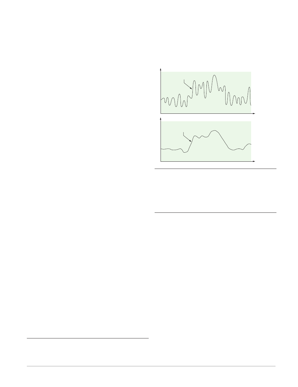
Filter Time Constant
Filtering smoothes an input signal by applying a
first-order filter time constant to the signal. Filter-
ing the displayed value makes it easier to monitor.
Filtering the signal may improve the performance of
PID control in a noisy or very dynamic system.
Adjust the filter time interval with Filter Time
[`FiL]
(Setup Page, Analog Input Menu). Example:
With a filter value of 0.5 seconds, if the process input
value instantly changes from 0 to 100 and remained at
100, the display will indicate 100 after five time con-
stants of the filter value or 2.5 seconds.
Filter Time Constant
Unfiltered Input Signal
Time
Temperature
Filtered Input Signal
Time
Temperature
Sensor Selection
You need to configure the controller to match the in-
put device, which is normally a thermocouple, RTD or
process transmitter.
Select the sensor type with Sensor Type [`Sen]
(Setup Page, Analog Input Menu).
Scale High and Scale Low
When an analog input is selected as process voltage
or process current input, you must choose the value
of voltage or current to be the low and high ends. For
example, when using a 4 to 20 mA input, the scale
low value would be 4.00 mA and the scale high value
would be 20.00 mA. Commonly used scale ranges are:
0 to 20 mA, 4 to 20 mA, 0 to 5V, 1 to 5V and 0 to 10V.
You can create a scale range representing other
units for special applications. You can reverse scales
from high values to low values for analog input sig-
nals that have a reversed action. For example, if 50
psi causes a 4 mA signal and 10 psi causes a 20 mA
signal.
Scale low and high low values do not have to match
the bounds of the measurement range. These along
with range low and high provide for process scaling
and can include values not measureable by the con-
troller. Regardless of scaling values, the measured val-
ue will be constrained by the electrical measurements
of the hardware.
Select the low and high values with Scale Low
[`S;Lo]
and Scale High [`S;hi]. Select the displayed
range with Range Low [`r;Lo] and Range High