Wiring, Wire, And connect the power source to the control – Watlow EZ-ZONE RM-Scanner-Modul User Manual
Page 22
Watlow EZ-ZONE
®
RMS Module
•
19
•
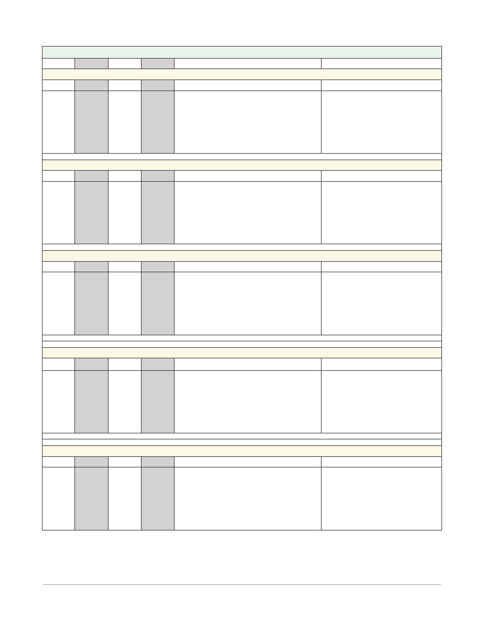
Chapter 2 Install and Wire
Scanner Module (R M S x - x x x x - x x x x)
Slot A
Slot B
Slot D
Slot E
Configuration
Universal, RTD and Thermistor Inputs 1 -16
1 - 4
5 - 8
9 - 12
13 - 16
S1
R1
S2
R2
S3
R3
S4
R4
S5
R5
S6
R6
S7
R7
S8
R8
S9
R9
S10
R10
S11
R11
S12
R12
S13
R13
S14
R14
S15
R15
S16
R16
S_ (RTD), thermocouple -, volts - , mA -, potenti-
ometer wiper or thermistor
R_ (RTD), thermocouple +, volts +, mA +, poten-
tiometer or thermistor
Universal/Thermistor Input
Part # Digits 5, 6, 7, 8
Input 1-4: RMSx-[R,P]xxx-xxxx
Input 5-8: RMSx-x[R,P]xx-xxxx
Input 9-12: RMSx-xx[R,P]x-xxxx
Input 13-16: RMSx-xxx[R,P]-xxxx
Digital Inputs 1 - 6 and 7 - 12
1 - 6
7-12
- - -
- - -
- - -
- - -
- - -
- - -
- - -
- - -
- - -
- - -
- - -
- - -
- - -
- - -
- - -
- - -
B1
D1
D2
D3
D4
D5
D6
Z1
B7
D7
D8
D9
D10
D11
D12
Z7
Common
DC +input
DC +input
DC +input
DC +input
DC +input
DC +input
Internal Supply
Digital Inputs (DI)
Part # Digit 7, 8
Slot A: Option not valid
Slot B: Option not valid
Slot D: RMSx-xx[C]x-xxxx
Slot E: RMSx-xxx[C]-xxxx
Digital Input 9
- - -
- - -
- - -
9
- - -
- - -
- - -
- - -
- - -
- - -
- - -
- - -
- - -
- - -
- - -
- - -
- - -
- - -
- - -
- - -
- - -
- - -
- - -
- - -
- - -
- - -
- - -
- - -
- - -
- - -
- - -
- - -
- - -
- - -
B9
D9
Common
DC +input
Digital Input (DI)
Part # Digit 8
Slot A: Option not valid
Slot B: Option not valid
Slot D: Option not valid
Slot E: RMSx-xxx[B]-xxxx
Form A - Mechanical Relay Outputs 1- 4 and 7 - 10
- - -
- - - -
1 - 4
7 - 10
- - -
- - -
- - -
- - -
- - -
- - -
- - -
- - -
- - -
- - -
- - -
- - -
- - -
- - -
- - -
- - -
L1
K1
L2
K2
L3
K3
L4
K4
L7
K7
L8
K8
L9
K9
L10
K10
normally open
common
normally open
common
normally open
common
normally open
common
Mechanical Relay 5 A, Form A
Part # Digits 7, 8
Slot D: : RMSx-xx[J]x-xxxx
Slot E: : RMSx-xxx[J]-xxxx
Digital Outputs 1 - 6 and 7 - 12
- - -
- - -
1 - 6
7 - 12
- - -
- - -
- - -
- - -
- - -
- - -
- - -
- - -
- - -
- - -
- - -
- - -
- - -
- - -
- - -
- - -
B1
D1
D2
D3
D4
D5
D6
Z1
B7
D7
D8
D9
D10
D11
D12
Z7
Common
open collector/ switched dc
open collector/ switched dc
open collector/ switched dc
open collector/ switched dc
open collector/ switched dc
open collector/ switched dc
Internal Supply
Digital Outputs (DO)
Part # Digit 7, 8
Slot A: Option not valid
Slot B: Option not valid
Slot D: RMSx-xx[C]x-xxxx
Slot E: RMSx-xxx[C]-xxxx
Wiring