Inputs 1 through 16 potentiometer, Inputs 1 through 16 process, Inputs 1 through 16 rtd – Watlow EZ-ZONE RM-Scanner-Modul User Manual
Page 27
Warning:
ç
Use National Electric (NEC) or other
country-specific standard wiring and
safety practices when wiring and
connecting this controller to a power
source and to electrical sensors or pe-
ripheral devices. Failure to do so may
result in damage to equipment and
property, and/or injury or loss of life.
Note:
Maximum wire size termination and
torque rating:
• 0.0507 to 3.30 mm2 (30 to 12 AWG)
single-wire termination or two 1.31
mm2 (16 AWG)
• 0.8 Nm (7.0 in-lb.) torque
Note:
Adjacent terminals may be labeled
differently, depending on the model
number.
Note:
To prevent damage to the controller,
do not connect wires to unused ter-
minals.
Note:
Maintain electrical isolation between
digital input-outputs, switched dc/open
collector outputs and process outputs
to prevent ground loops.
Warning:
ç
Explosion Hazard – Substitution of
component may impair suitability for
CLASS I, DIVISION 2.
Warning:
ç
Explosion Hazard - Do not disconnect
while the circuit is live or unless the
area is known to be free of ignitable
concentrations of flammable sub-
stances.
Watlow EZ-ZONE
®
RMS Module
•
24
•
Chapter 2 Install and Wire
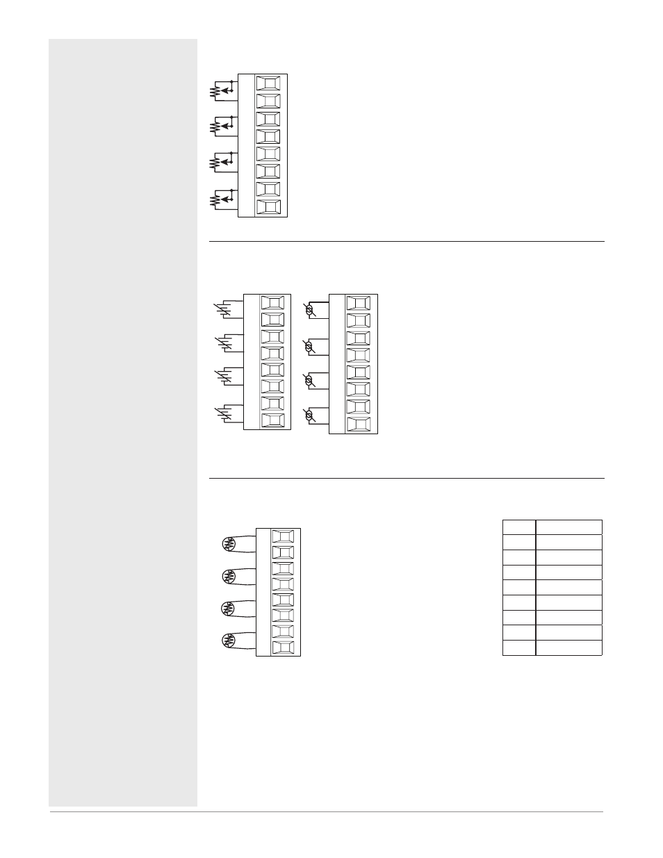
Inputs 1 through 16 Potentiometer
RMS Part # Digits 5, 6, 7, 8
S_
R_
S_
R_
S_
R_
S_
R_
Slot A, B, D, E
CW
CCW
CW
CCW
CW
CCW
CW
CCW
• Use a 1 kΩ potentiometer.
Input 1 - 4 (top to bottom): RMSx-(R)xxx-xxxx
Input 5 - 8 (top to bottom): RMSx-x(R)xx-xxxx
Input 9 - 12 (top to bottom): RMSx-xx(R)x-xxxx
Input 13 - 16 (top to bottom): RMSx-xxx(R)-xxxx
Inputs 1 through 16 Process
RMS Part # Digits 5, 6, 7, 8
-
+
-
+
-
+
-
+
S_
R_
S_
R_
S_
R_
S_
R_
volts
Slot A, B, D, E
-
+
-
+
-
+
-
+
S_
R_
S_
R_
S_
R_
S_
R_
amperes
Slot A, B, D, E
• 0 to 20 mA @ 100 Ω input impedance
• 0 to 10V
Î
(dc) @ 20 kΩ input impedance
• 0 to 50 mV
Î
(dc) @ 20 MΩ input impedance
• scalable
Input 1: RMS(1,3,5)xxxxxxxxxxx
(S1-/R1+),(T1+/S1-)
Input 2: RMSxx(1,5)xxxxxxxxx
(S2-/R2+),(T2+/S2-)
Input 3: RMSxxxx(1,5)xxxxxxx
(S3-/R3+),(T3-S3-R3)
Input 4: RMSxxxxxx(1,5)xxxxx
(S4-/R4+),(T4+/S4-)
Inputs 1 through 16 RTD
RMS Part # Digits 5, 6, 7, 8
2-wire
RTD
S_
R_
S_
R_
S_
R_
S_
R_
Slot A, B, D, E
• platinum, 100 and 1,000 Ω @ 0°C
• calibration to DIN curve (0.00385
Ω/Ω/°C)
• RTD excitation current of 0.09
mA typical. Each ohm of lead
resistance may affect the reading
by 2.55°C for a 100 ohm platinum
sensor or 2.5 ohms for a 1000
ohm sensor.
Input 1 - 4 (top to bottom): RMSx-
(R)xxx-xxxx
Input 5 - 8 (top to bottom): RMSx-
x(R)xx-xxxx
Input 9 - 12 (top to bottom): RM-
Sx-xx(R)x-xxxx
Input 13 - 14 (top to bottom):
RMSx-xxx(R)-xxxx
AWG
Ohms/1000ft
14
2.575
16
4.094
18
6.510
20
10.35
22
16.46
24
26.17
26
41.62
28
66.17