Rms installation and removal on a din rail – Watlow EZ-ZONE RM-Scanner-Modul User Manual
Page 20
Watlow EZ-ZONE
®
RMS Module
•
17
•
Chapter 2 Install and Wire
RMS Installation and Removal on a DIN Rail
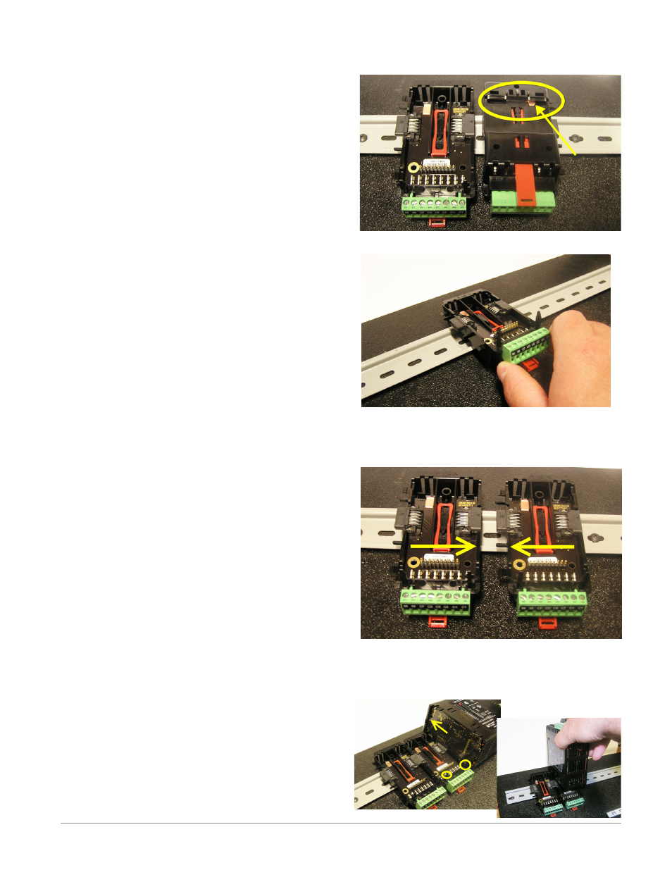
Modular Backplane Connector
The picture on the right shows the Modular Backplane
Connector, both front and rear view. The rear view
is bringing in to focus a metal clip. If the DIN rail is
grounded the Modular Backplane Connector and the
module connected to it will be also (recommended).
Installing the Modular Backplane Connector
Step 1
Hook backplane assembly to upper edge of DIN rail,
(see rear view above, backplane hook detail that
mates with upper rail edge is circled)
Step 2
Next, rotate back plane assembly downward to en
gage the lower edge of the rail. (Note: Din Rail clip-
ping distance ranges from 1.366 -1.389 inches. The
back plane assembly will not latch onto the rail suc-
cessfully if the rail is out of dimension).
Step 3
For final positioning and locking, the red tab is to
be pushed upward to further engage the bottom
edge of the rail with an over center snap action
latch. (The red locking tab protrudes from the bot-
tom side of the back plane assembly).
Installing Multiple Modular Backplane Connectors
Multiple modules are easily aligned and latched to-
gether. Each module includes matched mating geom-
etry that facilitates accurate and consistent intercon-
nections. The recommended method of multi-module
attachment is to first attach individual modules to
the rail separately and second to laterally slide the
modules together until they touch. (Refer to steps 1&2
above). When the multi-module system is attached and
laterally positioned to the desired placement the lock-
ing tab should be engaged to secure the control system
to the rail, (Refer to step 3 above).
Module Installation
In the picture to the right notice that the arrow is
pointing at the top lip of the module (on side). When in-
stalling the module simply slide this lip over the top of
the Modular Backplane Connector and then push down
on the rear of the module where it will seat on the two
posts just above the green connector.