Watlow EZ-ZONE RM-Scanner-Modul User Manual
Page 9
Watlow EZ-ZONE
®
RMS Module
•
6
•
Chapter 1 Overview
steps below to switch the RMS to the Standard bus
protocol.
1. Disconnect all Modbus devices from the network
2. Push and hold the orange button on the face of
the module for approximately 6 seconds
3. When the LED display (above the orange button)
changes to P [p] momentarily release the orange
button and then push it again where [S] will ap-
pear (symbol for Standard Bus), release the or-
ange button
4. Push the orange button again for approximately
3 seconds (LED display will become brighter) to
change the Standard Bus address if needed
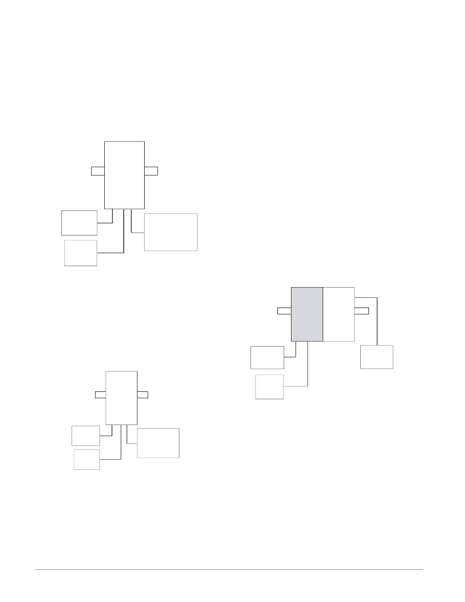
RMS Module Connected to an Operator Interface
Terminal (OIT) through an RMA
In this configuration the RMS can be connected to
the OIT through the RMA running any of a number
of available protocols. The RMA and the OIT must
be using the same protocol while the communications
from RMA to the RMS module is accomplished over
the backplane using Watlow's Standard Bus protocol.
Available protocols in the RMA follow:
1. EtherNet/IP and or Modbus TCP
2. DeviceNet
3. Modbus RTU
4. Profibus DP
Slot C
Slot C
RMS
Scanner
RM
Access
Slot
E
RUI
OIT
Power
Supply
Notice that in the example above that there is an op-
tional RUI connected to the RMS along with the OIT.
OITs' are not generally used to configure a control
but are used more for run-time information. As an al-
ternative for configuration the RUI could be used to
configure and monitor in a remote location.
One advantage in using an RMA module when com-
municating on a network is that protocol switching
is not needed on the RMS module if using an RUI
or EZ-ZONE Configurator software. The protocol of
choice used with the RMA can run simultaneously
with the Standard Bus protocol.
RMS Connected to a Split Rail with OIT
In this configuration both the inter-module bus
(backplane communications) and Standard Bus are
A Conceptual View of RM Hardware Configurations
Due to the scalability and flexibility in the RM sys-
tem a user has several options available in the way
that the hardware can be connected. Listed below
are a few examples.
RMS Connected to a Remote User Interface (RUI)
and a Personal Computer (PC)
In this configuration the RUI and PC are connected
to the RMS module via Watlow's Standard Bus where
both will be able to talk directly to the RMS module.
RMS
Scanner
Slot C
Power
Supply
RUI
PC Running
EZ-ZONE
Configurator
In the graphic above the PC running EZ-ZONE Con-
figurator software and or the RUI can be used to
configure and then monitor the RMS and other mod-
ules connected to it.
RMS Module Connected to a Programmable Logic
Controller (PLC) on a DIN Rail
In this configuration the PLC can be connected to
the RMS module using the Modbus RTU protocol:
RMS
Scanner
Slot C
Power
Supply
PLC
PC Running
EZ-ZONE
Configurator
In this example, the RMS module and the PLC must
be equipped with the Modbus RTU protocol.
Note:
If it is intended to use an RUI or a PC using EZ-
ZONE Configurator software it will be necessary to
switch the protocol on the RMS to Watlow's Stan-
dard Bus to successfully communicate; follow the