Watlow EZ-ZONE RM-Scanner-Modul User Manual
Page 23
Watlow EZ-ZONE
®
RMS Module
•
20
•
Chapter 2 Install and Wire
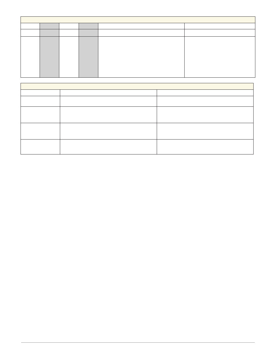
Form C - Mechanical Relay Output 7 and Form A - Mechanical Relay Output 8
Slot A
Slot B
Slot D
Slot E
Configuration
- - -
- - - -
- - -
7 and 8
- - -
- - -
- - -
- - -
- - -
- - -
- - -
- - -
- - -
- - -
- - -
- - -
- - -
- - -
- - -
- - -
- - -
- - -
- - -
- - -
- - -
- - -
- - -
- - -
L7
K7
J7
L8
K8
- - -
- - -
- - -
normally open
common
normally closed
normally open
common
Form C and Form A Relay Outputs
Part # Digit 8
Slot A: Option not valid
Slot B: Option not valid
Slot D: Option not valid
Slot E: RMSx-xxx[B]-xxxx
Power and Communications
Slot C
Configuration
98
99
Power input: ac or dc+
Power input: ac or dc-
All
CF
CD
CE
Standard Bus EIA-485 common
Standard Bus EIA-485 T-/R-
Standard Bus EIA-485 T+/R+
Standard Bus
Part # Digit 10
RMSx-xxxx-x[A]xx
CC
CA
CB
Standard Bus or Modbus RTU EIA-485 common
Standard Bus or Modbus RTU EIA-485 T-/R-
Standard Bus or Modbus RTU EIA-485 T+/R+
Standard Bus or Modbus
Part # Digit 10
RMSx-xxxx-x[1]xx
CZ
CX
CY
Inter-module Bus
Inter-module Bus
Inter-module Bus
Inter-module Bus