Getting started quickly – Watlow EZ-ZONE RM-Scanner-Modul User Manual
Page 11
Watlow EZ-ZONE
®
RMS Module
•
8
•
Chapter 1 Overview
Getting Started Quickly
Consider taking the following steps to quickly com-
mission your control:
• Wire
and connect the power source to the control
• Wire and connect input and output devices to the
control
• Power up the control and navigate to the Setup
Page to configure inputs, outputs, adjust set
points, alarms, etc...
The RMS controller has a page and menu structure
that is listed below along with a brief description of
its purpose. The menu structure can be easily seen
and navigated using
or the Remote User Interface (RUI).
Note:
The menu navigation as described below applies
when the RMS is connected to the RUI which is op-
tional equipment.
Setup Page
Using the RUI, push
and hold the up and
down keys (¿ ¯) for 6
seconds to enter. (See
the
for fur-
ther information)
A user would want to
setup their control prior
to operation. As an ex-
ample, define the input
type, alarm sides (high
and or low) or set the
output function.
Operations Page
Using the RUI push and
hold the up and down
keys (¿ ¯) for 3 seconds
to enter. (See the
for further
information)
After setting up the
control to reflect your
equipment, the Op-
erations Page would
be used to monitor or
change runtime settings.
As an example, the user
may want to see the cur-
rent status (on or off) of
an event in the Action
Menu.
Factory Page
Using the RUI push and
hold the Infinity and
the green Advance keys
(ˆ
‰
) for 6 seconds to
enter. (See the
for further infor-
mation)
For the most part the
Factory Page has no
bearing on the con-
trol when running. A
user may want to en-
able password protec-
tion, view the control
part number or perhaps
create a custom Home
Page.
Home Page
When using the RUI,
the control is at the
Home Page
when ini-
tially powered up where
it will display the value
of Analog Input 1 in the
upper display and the
value of Analog Input 2
in the lower display.
Note:
The Home Page is vis-
ible only when using
the RUI.
Pushing the green Ad-
vance Key
‰
will cause
the display to show the
value of Analog Input 1
in the upper display and
Analog Input 2 in the
lower display. With each
successive push of the
green advance key the
display will sequentially
show the value of all
remaining analog inputs
in the upper display and
the lower display will
show the correspond-
ing LED display. (e.g.,
[AIN3]
for input 3)
The default RMS loop configuration out of the box is
shown below:
• All Analog Input functions are set to thermocou-
ple, type J (to change go to the Setup Page, Ana-
log Input Menu)
• All Process Value functions are set to off (to
change go to the Setup Page, Process Value
Menu)
• All outputs are set to off (to change go to the Set-
up Page, Output Menu)
Once the scanner has been wired and setup, power
up the control. If using an RUI the upper display will
show the value of Analog Input 1 and the lower dis-
play will show the value of Analog Input 2.
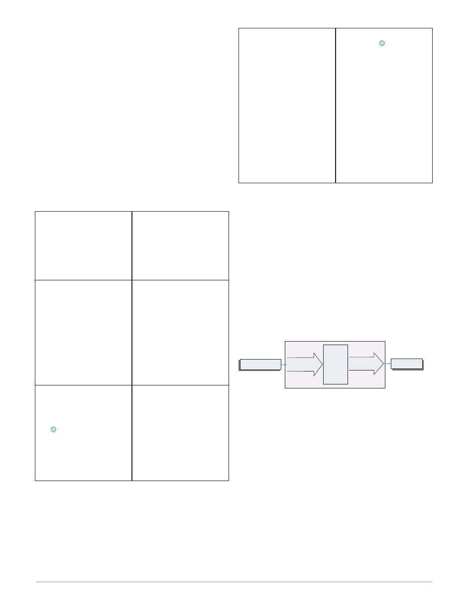
EZ-ZONE RMS Default Configuration
Off
Thermocouple Type J
All Analog Inputs
Alarm
Types
Off
Input Sensor
Output
Function
Input
Function
All Outputs