Saving and restoring user settings, Inputs, Saving and restoring user settings inputs – Watlow EZ-ZONE RM-Scanner-Modul User Manual
Page 89: Calibration offset, Calibration
Watlow EZ-ZONE
®
RMS Module
•
86
•
Chapter 6 Features
Saving and Restoring User Settings
Recording setup and operations parameter settings
for future reference is very important. If you uninten-
tionally change these, you will need to program the
correct settings back into the controller to return the
equipment to operational condition.
After you program the controller and verify prop-
er operation, use User Save Set [USr;S] (Setup Page,
Global Menu) to save the settings into either of two
files in a special section of memory. If the settings
in the controller are altered and you want to return
the controller to the saved values, use User Restore
Set [USr;r] (Setup Page, Global Menu) to recall one
of the saved settings. A digital input or the Function
Key can also be configured to restore parameters.
Note:
Starting with firmware release 6, there is only one
user set.
Note:
Only perform the above procedure when you are
sure that all the correct settings are programmed
into the controller. Saving the settings overwrites
any previously saved collection of settings.
Be sure to document all the controller settings.
Note:
When restoring factory defaults, I/O assemblies for
Modbus, DeviceNet, Profibus and Ethernet along
with the zone address will be overwritten when re-
storing factory defaults.
Inputs
Calibration Offset
Calibration offset allows a device to compensate for
an inaccurate sensor, lead resistance or other factors
that affect the input value. A positive offset increases
the input value, and a negative offset decreases the
input value.
The input offset value can be viewed or changed
with Calibration Offset [`i;CA] (Operations Page,
Analog Input Menu).
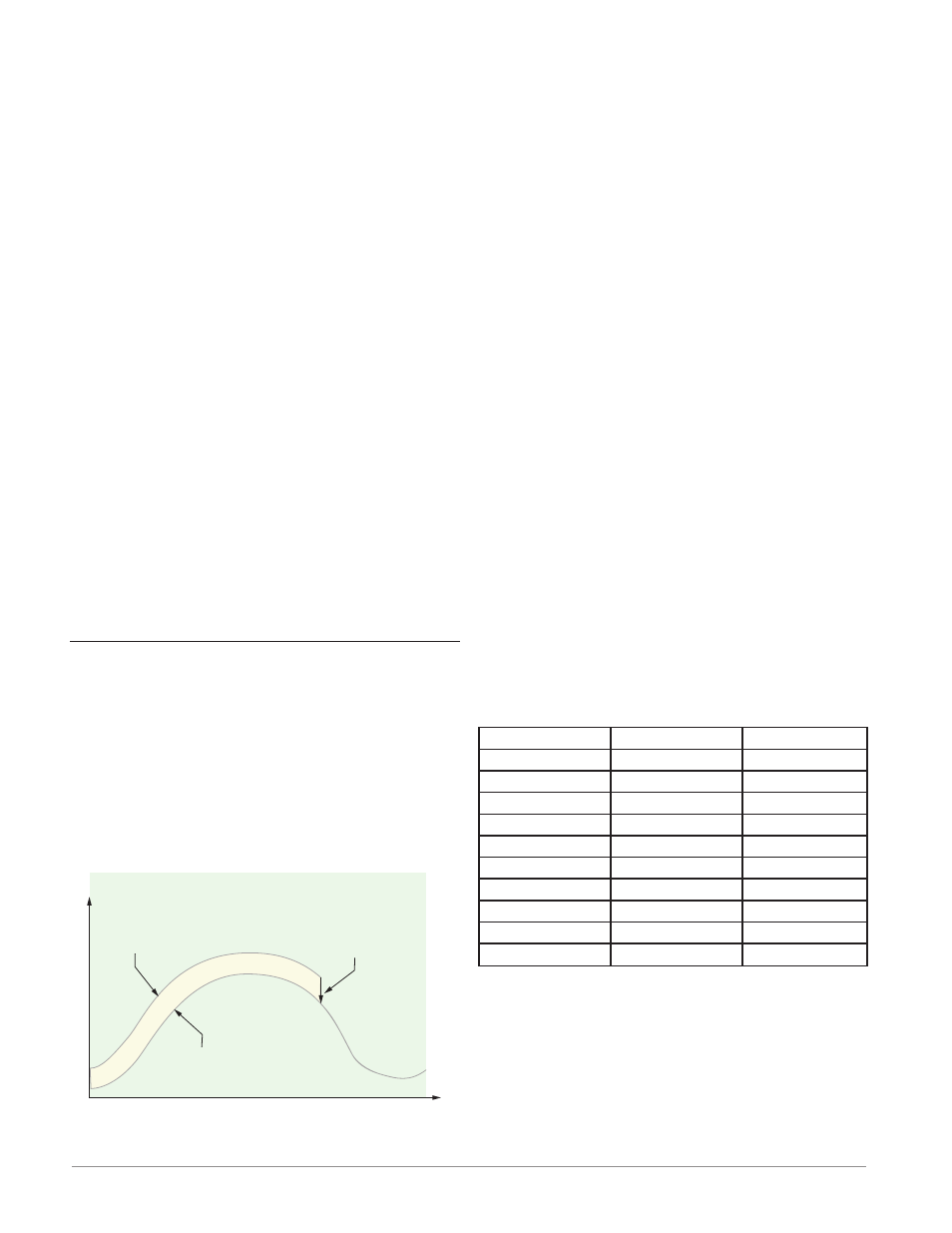
Time
Temperature
Temperature Reading
from Sensor
Actual Process Temperature
Negative Calibration Offset will
compensate for the difference
between the Sensor Reading and
the Actual Temperature
Calibration
Before performing any calibration procedure, verify
that the displayed readings are not within published
specifications by inputting a known value from a pre-
cision source to the analog input. Next, subtract the
displayed value with the known value and compare
this difference to the published accuracy range speci-
fication for that type of input.
Use of the Calibration Offset [`i;CA] parameter
found in the Operations Page [oPEr] , Analog Input
Menu [``Ai] shifts the readings across the entire
displayed range by the offset value. Use this param-
eter to compensate for sensor error or sensor place-
ment error. Typically this value is set to zero.
Equipment required while performing calibra-
tion: Obtain a precision source for millivolts, volts,
milliamperes or resistance depending on the sensor
type to be calibrated. Use copper wire only to connect
the precision source to the controller’s input. Keep
leads between the precision source and controller as
short as possible to minimize error. In addition, a
precision volt/ohm meter capable of reading values to
4 decimal places or better is recommended. Prior to
calibration, connect this volt/ohm meter to the preci-
sion source to verify accuracy.
Actual input values do NOT have to be exactly the
recommended values, but it IS critical that the actual
value of the signal connected to the controller be ac-
curately known to at least four digits.
Calibration of Analog Inputs:
To calibrate an analog input, you will need to provide
a source of two electrical signals or resistance values
near the extremes of the range that the application is
likely to utilize. See recommended values below:
Sensor Type
Low Source
High Source
thermocouple
0.000 mV
50.000 mV
millivolts
0.000 mV
50.000 mV
volts
0.000V
10.000V
milliamps
0.000 mA
20.000 mA
100 Ω RTD
50.00 Ω
350.00 Ω
1,000 Ω RTD
500.00 Ω
3,500.00 Ω
Thermistor 5K
50.00 Ω
5000.00 Ω
Thermistor 10K
50.00 Ω
10000.00 Ω
Thermistor 20K
50.00 Ω
20000.00 Ω
Thermistor 40K
50.00 Ω
40000.00 Ω
Note:
The user may only calibrate one sensor type. If the
calibrator interferences with open thermocouple
detection, set Sensor Type [`SEn] in Setup Page
[`SEt]
, Analog Input Menu [``Ai] to millivolt
[`Mu]
instead of Thermocouple [``tC] to avoid
interference between the calibrator and open ther-
mocouple detect circuit for the duration of the cali-
bration process. Be sure to set sensor type back to
the thermocouple type utilized.
1. Disconnect the sensor from the controller.