Watlow ez-zone, Rms module, Chapter 1 overview – Watlow EZ-ZONE RM-Scanner-Modul User Manual
Page 12
Watlow EZ-ZONE
®
RMS Module
•
9
•
Chapter 1 Overview
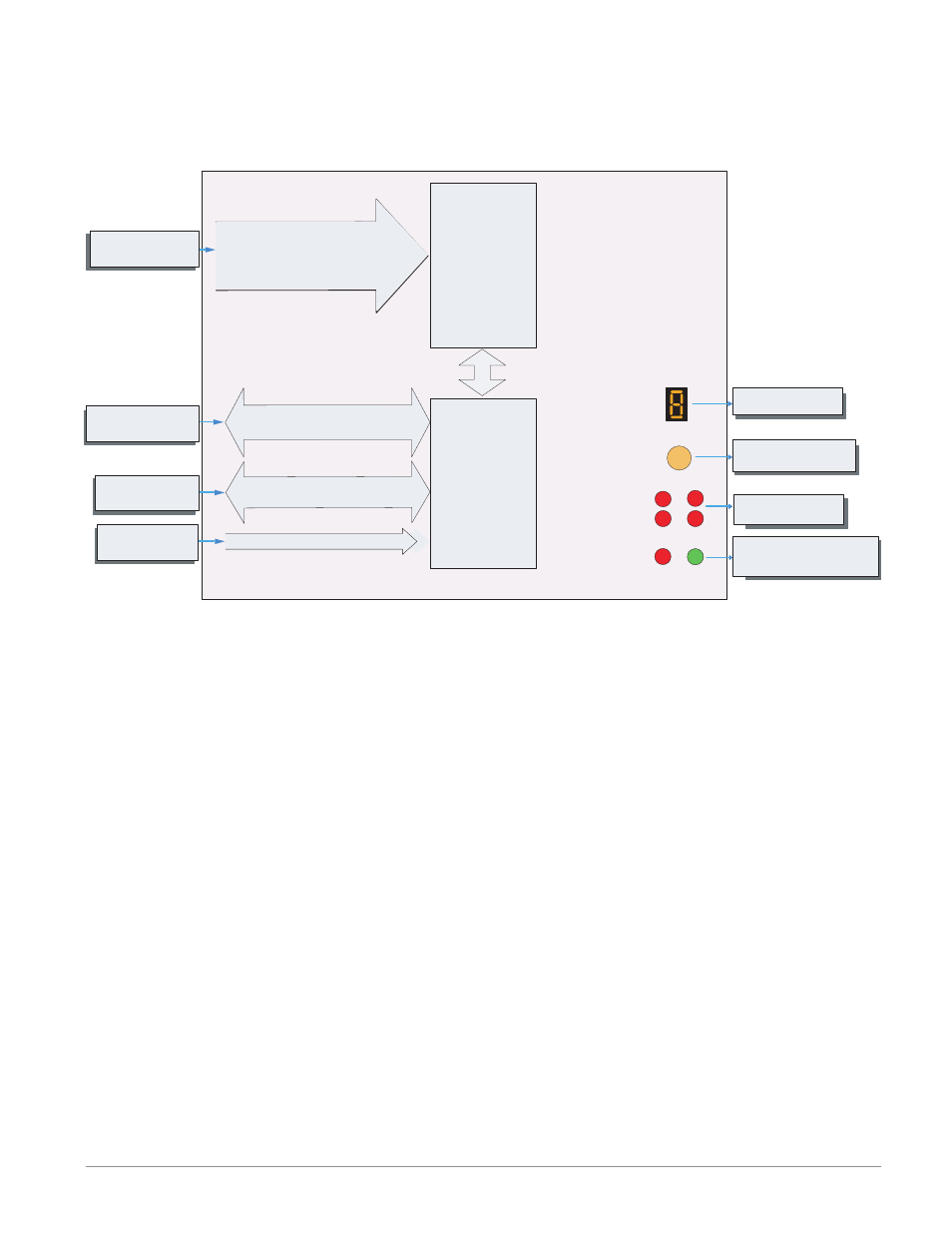
EZ-ZONE RMS Module - System Diagram
16 Scanner Channels - Slots A, B, D and E
R M S x - [R,P] [R,P] [R,P] [R,P] - A A A A
Push to select Zone
Address and Protocol
None, Thermocouple, 2-Wire RTD (100, 1k),
Thermistor (5k, 10K, 20k, 40k), Process
(V, mV, mA) or 1K Potentiometer
Analog Input 1 through 16
Alarms
Output
Function
Input
Function
Zone and Status
LED
Zone Selection
Button
D
E
B
A
S
M
EIA - 485 Communications
Standard Bus
(optional Modbus RTU)
Inter-module Bus
Indicates Zone
Address
Card Status
Slots A, B, D, E
RUI,
PC, PLC or HMI
Other RM Modules
Power Supply
Modbus RTU
Address 1 - 16
Standard Bus
Zone 1 - 16
Supervisory &
Power Board
Slot C
20.4 to 30.8 Vac or Vdc
Indicates communications
activity (Modbus or Stand-
ard Bus)
Slot A, B, D, E
Input Sensor
- 12LS Controller (111 pages)
- 8LS Controller (140 pages)
- 8PID Controller (55 pages)
- Addendum to EZwarePlus (50 pages)
- ANASCAN (62 pages)
- ANASOFT (95 pages)
- ANAWIN 2 (154 pages)
- ANAWIN 3 (23 pages)
- Calibrating Watlow Series 988 Family Process Controls (19 pages)
- CAS (98 pages)
- CAS200 (124 pages)
- CLS (180 pages)
- CLS200 (251 pages)
- CLS200, MLS300 and CAS200 (92 pages)
- Control Console (12 pages)
- CPC400 (230 pages)
- DIN-A-MITE Style A (9 pages)
- DIN-A-MITE Style B (14 pages)
- DIN-A-MITE Style C (22 pages)
- DIN-A-MITE Style D (9 pages)
- DIN-Mount Adapter Instruction Sheet, Rev A (1 page)
- Dual DAC (4 pages)
- EM Gateway (28 pages)
- E-Safe Hybrid Relay Rev B (4 pages)
- E-SAFE II Hybrid Power Switch (4 pages)
- EZwarePlus Programming (264 pages)
- EZ-ZONE PM (111 pages)
- EZ-ZONE PM PID (125 pages)
- EZ-ZONE PM Express Limit (34 pages)
- EZ-ZONE PM Express (35 pages)
- EZ-ZONE PM Integrated Controller (181 pages)
- EZ-ZONE RM Limit Module Rev C (127 pages)
- EZ-ZONE RMA Modul (79 pages)
- EZ-ZONE RMC (236 pages)
- EZ-ZONE RME (124 pages)
- EZ-ZONE RMH (161 pages)
- EZ-ZONE RUI/Gateway (62 pages)
- EZ-ZONE ST (97 pages)
- F4 External Event Board - Rev.B (2 pages)
- HG Series Mercury Displacement Relay (6 pages)
- LogicPro (296 pages)
- Mercury Relay or MDR Retrofit (13 pages)
- MICRODIN (106 pages)
- MICRODIN (24 pages)