1 at power select jumper settings, Table 4-1: jumpers – IEI Integration WAFER-945GSELVDS2 User Manual
Page 59
WAFER-945GSELVDS2
Page 47
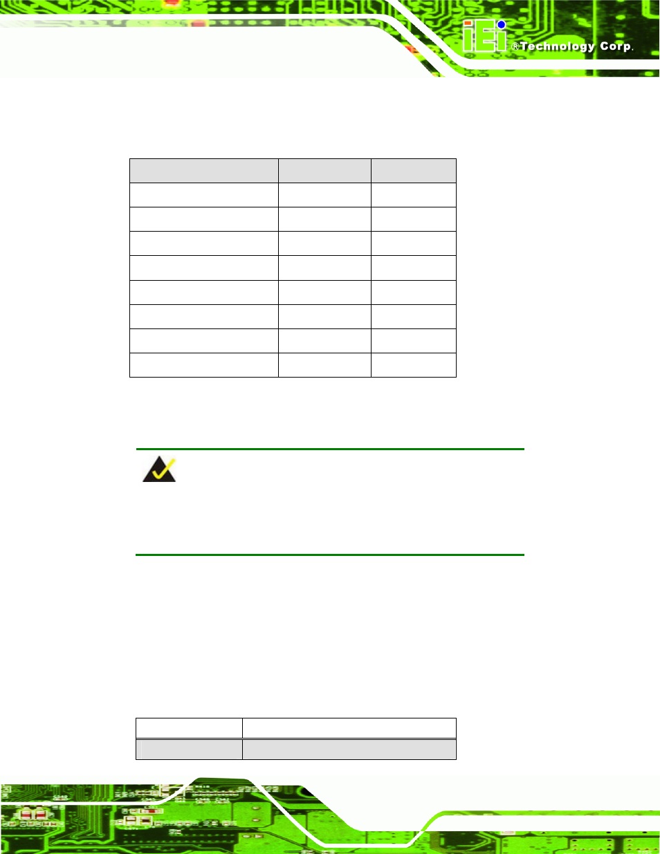
Before the WAFER-945GSELVDS2 is installed in the system, the jumpers must be set in
accordance with the desired configuration. The jumpers on the WAFER-945GSELVDS2
are listed in Table 4-1.
Description
Label
Type
AT Power Mode Setting
ATXCTL1
2-pin header
Audio Power Source
JP2
3-pin header
CF Card Setting
JCF1
2-pin header
Clear CMOS
J_CMOS1
3-pin header
COM2 Mode Setting
JP1
6-pin header
LVDS1 Panel Resolution
J_LCD_TYPE1
8-pin header
LVDS1 voltage selection
J_VLVDS1
3-pin header
LVDS2 voltage selection
J_VLVDS2
3-pin header
Table 4-1: Jumpers
4.6.1 AT Power Select Jumper Settings
NOTE:
The AT Power Select Jumper is the same as the ATX Enable
connector.
Jumper Label:
ATXCTL1
Jumper Type:
3-pin header
Jumper Settings:
Jumper Location:
Sets the system to use AT or ATX power. When set to ATX power, the power switch cable
must be connected to this jumper.
Pin Description
2-3
Use AT power
- SPCIE-5100DX (180 pages)
- SPCIE-C2060 v1.01 (200 pages)
- SPCIE-C2060 v2.12 (212 pages)
- SPCIE-C2160 (204 pages)
- SPCIE-C2260-i2 (217 pages)
- ROCKY-3786 v4.0 (175 pages)
- ROCKY-3786 v4.10 (147 pages)
- PCIE-Q350 v1.00 (272 pages)
- PCIE-Q350 v1.12 (250 pages)
- PCIE-Q350 v1.20 (250 pages)
- PCIE-Q350 v1.30 (213 pages)
- PCIE-Q57A (159 pages)
- PCIE-G41A2 (151 pages)
- PCIE-Q670 v1.03 (206 pages)
- PCIE-Q670 v2.00 (205 pages)
- PCIE-H610 (181 pages)
- PCIE-Q870-i2 (217 pages)
- IOWA-LX-600 (159 pages)
- PCISA-945GSE v1.01 (207 pages)
- PCISA-945GSE v1.10 (190 pages)
- PCISA-9652 v1.00 (232 pages)
- PCISA-9652 v1.01 (232 pages)
- PCISA-PV-D4251_N4551_D5251 (145 pages)
- PICOe-945GSE (197 pages)
- PICOe-GM45A (198 pages)
- PICOe-PV-D4251_N4551_D5251 v1.00 (154 pages)
- PICOe-PV-D4251_N4551_D5251 v1.10 (154 pages)
- PICOe-PV-D4251_N4551_D5251 v1.11 (155 pages)
- PICOe-B650 (156 pages)
- PICOe-HM650 (174 pages)
- HYPER-KBN (139 pages)
- SPXE-14S (3 pages)
- SPXE-9S v1.00 (5 pages)
- SPXE-9S v1.1 (6 pages)
- SPE-9S v1.00 (4 pages)
- SPE-9S v1.1 (5 pages)
- SPE-6S (3 pages)
- SPE-4S (4 pages)
- PE-6SD3 (4 pages)
- PE-6SD2 v4.0 (4 pages)
- PE-6SD2 v2.10 (3 pages)
- PE-6SD (3 pages)
- PE-6S3 v1.0 (2 pages)
- PE-6S3 v4.0 (4 pages)
- PE-6S2 (4 pages)