1 northbridge configuration, Bios menu 23:northbridge chipset configuration – IEI Integration WAFER-945GSELVDS2 User Manual
Page 117
WAFER-945GSELVDS2
Page 105
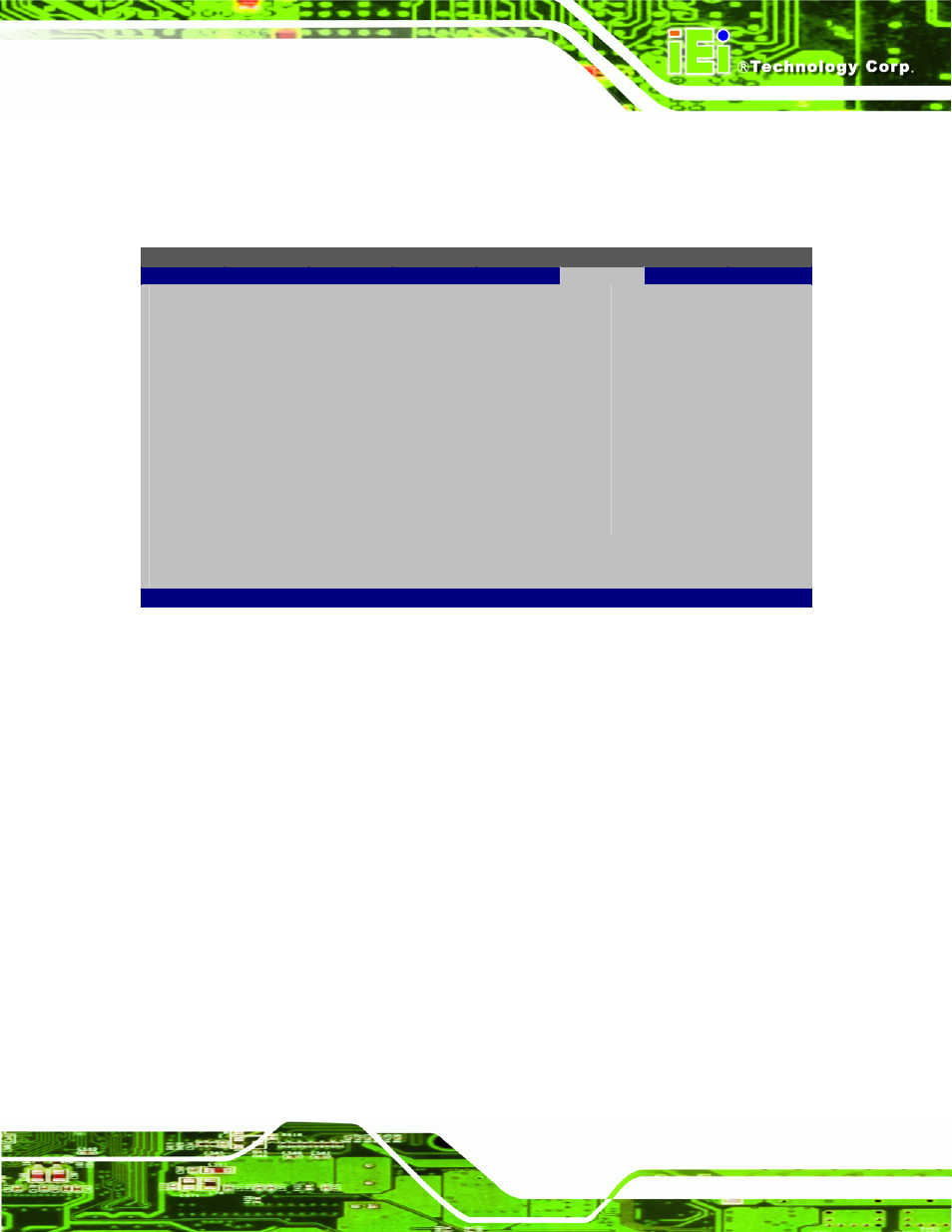
5.7.1 Northbridge Configuration
Use the Northbridge Chipset Configuration menu (BIOS Menu 23) to configure the
Northbridge chipset.
BIOS SETUP UTILITY
Main
Advanced
PCIPNP
Boot
Security
Chipset
Exit
Northbridge Configuration
⎯⎯⎯⎯⎯⎯⎯⎯⎯⎯⎯⎯⎯⎯⎯⎯⎯⎯⎯⎯⎯⎯⎯⎯⎯⎯⎯⎯⎯⎯⎯
Memory Hole
[Disabled]
Internal Graphics Mode Select
[Enabled, 8MB]
Video Function Configuration
⎯⎯⎯⎯⎯⎯⎯⎯⎯⎯⎯⎯⎯⎯⎯⎯⎯⎯⎯⎯⎯⎯⎯⎯⎯⎯⎯⎯⎯⎯⎯
DVMT Mode Select
[DVMT Mode]
DVMT/Fixed Memory
[128MB]
Boot Display Device
[CRT]
LVDS1 Panel Type
[by H/W]
LVDS1 Current Jumper Setting
[1280x1024 36b]
LVDS2 Panel Type
[by H/W]
LVDS2 Current Jumper Setting
[1024x768 18b]
Options
Disabled
15MB-16MB
ÅÆ Select
Screen
↑ ↓ Select
Item
Enter Go to SubScreen
F1 General
Help
F10
Save and Exit
ESC Exit
v02.61 ©Copyright 1985-2006, American Megatrends, Inc.
BIOS Menu 23:Northbridge Chipset Configuration
Memory Hole [Disabled]
Use the Memory Hole option to reserve memory space between 15 MB and 16 MB for
ISA expansion cards that require a specified area of memory to work properly. If an older
ISA expansion card is used, please refer to the documentation that came with the card to
see if it is necessary to reserve the space.
Î
Disabled D
EFAULT
Memory is not reserved for ISA expansion cards
Î
15 MB–16 MB
Between 15 MB and 16 MB of memory is reserved
for ISA expansion cards
Internal Graphics Mode Select [Enable, 8 MB]
Use the Internal Graphic Mode Select option to specify the amount of system memory
that can be used by the Internal graphics device.