Ransburg, Mma-570 direct/indirect charge - maintenance – Ransburg MMA-570 Direct_Ind Charge Atomizer A13366 User Manual
Page 72
CHECKING PROBES
Check atomizer voltage using the Ransburg Test
Meter Kit (76652-01 or 76652-04). Verify that the
output voltages have not varied much from the
setup standard. A drastic change in voltage can
be an early indicator of a component or system
problem. The data shown was collected under
the ideal lab conditions using a clean atomizer
and an unloaded fluid delivery system.
The following data is for use with the MMA-570. The
output voltage measured at the bell will normally
range between 91% and 97% of the kV set-point
displayed at the control unit. Typical setting for
spraying is 70 kV.
High Voltage Ring Inspection
Examine entire ring for burning marks indicated
by melted plastic or blackened areas around or
near where the electrodes are located, the area
where the high voltage input tube is, and on the
inner diameter of the ring.
If any area is found with the above conditions, the
ring must be replaced.
After verifying, clean all old dielectric grease from
the eight (8) protrusions on the front of the ring
and from the concentric circles at the high voltage
input protrusion.
Re-apply dielectric grease (LSCH0009) to both of
these areas. The eight (8) protrusions only require
a thin film of grease. The high voltage input area
must be filled with grease allowing no air voids.
Excess grease will be squeezed out when the
input tube and high voltage cable are installed.
Wipe off all excess grease.
High Voltage Ring Lubrication
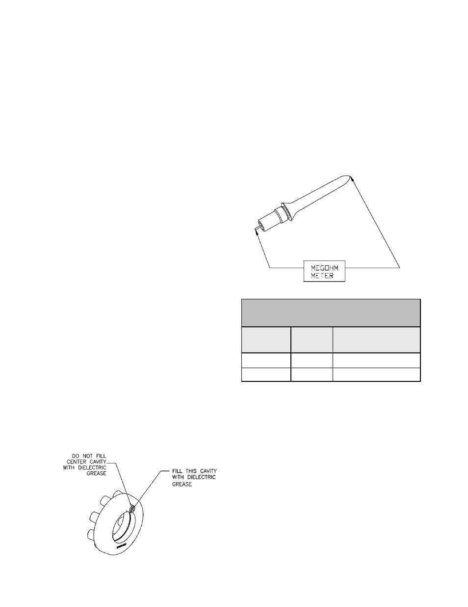
ELECTRODE RESISTANCE TEST
To verify that all indirect charge electrodes are
functioning, place one lead of a Yokogama meg-
ohm meter or equivalent to the metal contact at
the base of the electrode and the other end to
the small metal wire at the tip of the electrode.
Refer to the “Electrode Assembly Resistance
Reading” chart for the proper resistance reading
for the electrode assembly.
If readings fall out of this range, disassemble elec-
trode assembly and check reading of resistor only.
If reading is in the acceptable range, discard the
electrode body (A11342-00) and replace with a
new one. Rebuild electrode assembly as follows:
apply a small amount of dielectric grease to each
end of the resistor, slide resistor into the electrode
body (A11342-00). Install the contact assembly
after the resistor. Finally, apply a small amount of
dielectric grease to contact area of plunger contact
assembly. Thread plunger contact assembly into
electrode body by hand until it stops. Hand-tight
is good enough. Over-tightening will damage
the electrode body (see “Disassembly/Assembly
Electrode Assembly” figure).
A11343-02 209-231 Sea Level
A11343-03 129-151 Above 5,000 ft.
ELECTRODE ASSEMBY
RESISTANCE READING
Part No.
Used At (Locations)
Resistance
Reading
(Megohms)
MMA-570 Direct/Indirect Charge - Maintenance
Ransburg
LN-9279-13
69