Air tubing connections, Equipment grounding / safety recommendations, Ransburg – Ransburg MMA-570 Direct_Ind Charge Atomizer A13366 User Manual
Page 31
With the exception of fluid, dump, and
bearing air, all other pilot and air supply
lines should be bulkheaded and their di-
ameters increased one size.
EQUIPMENT GROUNDING /
SAFETY RECOMMENDATIONS
In electrostatic coating systems, the flow of high
voltage power from the power supply to the
atomizer is insulated from ground and isolated
from all other functions equipment. When the
voltage reaches the atomizer, it is transferred
to the coating material where, by introducing a
negative charge, it causes the atomized fluid to
seek the nearest positive ground. In a properly
constructed and operated system, that ground will
be the target object.
The directed conduction of the electric charge,
through its array of wires, cables, and equipment,
is accompanied by a variety of stray electrical
charges passing through the air by various means
such as: air ionization, charged particles in the
air and radiated energy. Such charges may be
attracted to any conductive material in the spray
area. If the conductive material does not provide
a safe drain to electrical ground, which will allow
the charge to dissipate as fast as it accumulates,
it may store the charge. When its electrical stor-
age limit is reached, or when it is breached by
external circumstances (such as the approach
of a grounded object or person, or one at lower
potential), it may discharge its stored charge to
the nearest ground. If there is no safe path to
ground (such as a ground wire or braided cable) it
may discharge through the air as a spark. A spark
may ignite the flammable atmosphere of a spray
area. The hazard area extends from the point
of origin up to as much as a twenty-foot radius.
(See the NFPA-33 for definition and limitations of
a hazard area.)
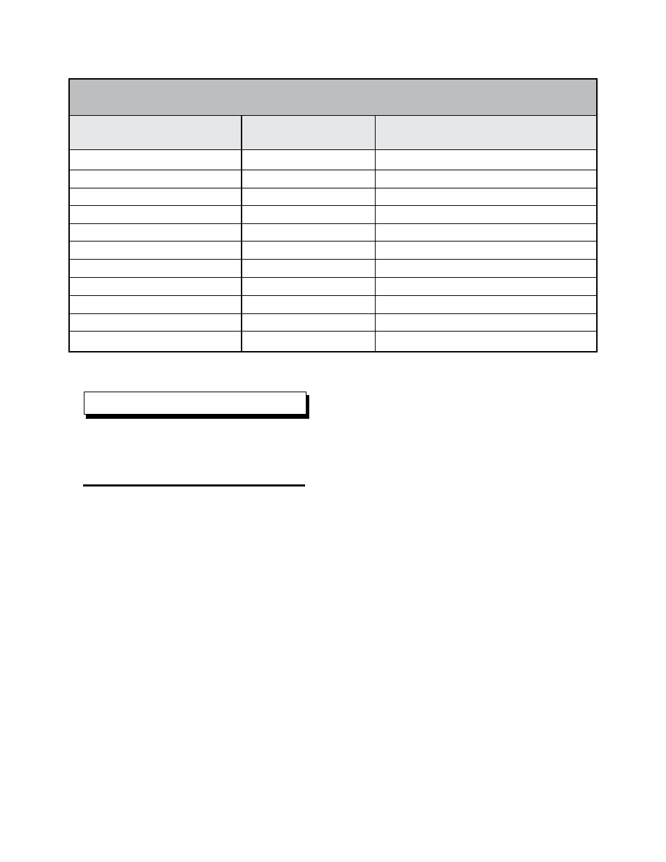
AIR TUBING CONNECTIONS
Tube Size
Air Pressure Requirements
Beaning Air Supply (B.A.)
6 X 4 mm (Yellow)
90 psi +/- 10 kPa (621 +/- 69 kPa)
Bearing Air Return (BRG RTN)
4mm (5/32”) OD (Yellow)
90 psi +/- 10 (at atomizer card 621 +/- 69 kPa)
Turbine Air (T.A.)
12 X 10mm
Variable
Outer Air (SAO)
8 X 6mm
Variable
Pattern Control Air (SAI)
10 X 8mm (Blue)
Variable
Brake Air (BRK) (if used)
6 X 4mm (Orange)
60-100 psi (414-689 kPa)
Paint Valve Control (PT)
4mm (5/32”) OD (Natural)
80 psi +/- 10 (552 +/- 70 kPa)
Dump Valve Control (PD)
4mm (5/32”) OD (Gray)
80 psi +/- 10 (352 +/- 70 kPa)
Cup Wash Solvent Valve Control (ST)
4mm (5/32”) OD (Blue)
80 psi +/- 10 (352 +/- 70 kPa)
Cup Wash Air Valve Control (ATI)
4mm (5/32”) OD (Orange)
80 psi +/- 10 (352 +/- 70 kPa)
Cup Wash Air (CWA)
6 X 4mm (Green)
80-100 psi (551-689 kPa)
NOTE
MMA-570 Direct/Indirect Charge - Installation
Ransburg
LN-9279-13
28