Protective covers, Ransburg, Mma-570 direct/indirect charge - operation – Ransburg MMA-570 Direct_Ind Charge Atomizer A13366 User Manual
Page 48
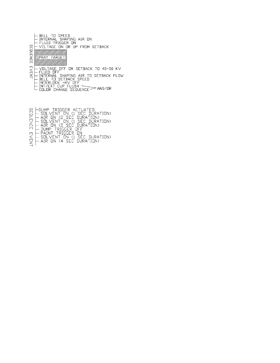
Typical Paint Sequence
Typical Color Change Sequence
Sequence Event Explanation:
1. Bell to Speed - This is accomplished by a set
point command from either the PLC, robot, or
other input device, through the I/O module.
2. Shaping Air - Set to 350-400 SCFM
w h i l e p e r f o r m i n g a c u p f l u s h .
3. Voltage On - The voltage is turned on from
a signal to the MicroPak. The lag time to
full voltage may be reduced if a setback
voltage is used. Recommended setback
voltage is between 30 kV and 50 kV.
4. Trigger Fluid - An air signal is sent through
the PT line of the tubing bundle. This should
occur when the target is 6-12-inches (152.4-
304.8mm) from the applicator centerline.
(Not to be confused with target distance.)
5. Voltage Off/Setback Voltage - Immediately
precedes the trigger off. Using a setback volt-
age shortens the cascade voltage ramp up time.
6. Fluid Trigger Off - This should occur
when the target is typically 0-6-inches (0-
152.4mm) past the applicator centerline.
7. Shaping Air to Setback - The setback
flow of air should never be below 70 slpm
(2.6 SCFM) for the inner shape air except
when performing a cup flush sequence.
8. Color Change Sequence - Used when
color is changed one to the other. Typical
sequence is shown in “Typical Color Change
Sequence” figure in the “Operation” section.
(Note: During this sequence, the applicator
should be moved to a position to collect
the waste material.) The sequence shown
is a starting point for processing, but the final
sequence will depend on the material being
sprayed and the solvent used to purge the
applicator with.
PROTECTIVE COVERS
It is recommended to use covers to reduce the
amount of overspray build-up on the shroud and
electrodes. Two covers are available, a white lint
free stretch cloth for covering the probes and a foam
cover (green) for the front shaping air shroud. The
white cloth cover should cover all of the electrode
except for the last 1-inch (25-4mm). The green
foam cover should be installed until just past the
radius edge of the shroud. Care is to be taken
when installing the white cloth covers over the
electrodes, do not bend them. (Devise a fixture
to help slide the cover over easier.).
When cleaning, do not get covers wet, it will attract
more overspray, more quickly. Push them back,
clean surface, dry thoroughly, and slide back to
original position. Depending on conditions, covers
should be replaced after each shift (8 hours).
A11565-00 White Stretch, Lint Free Covers
A11564-00 - Foam Elastic Covers (Green)
MMA-570 Direct/Indirect Charge - Operation
Ransburg
LN-9279-13
45